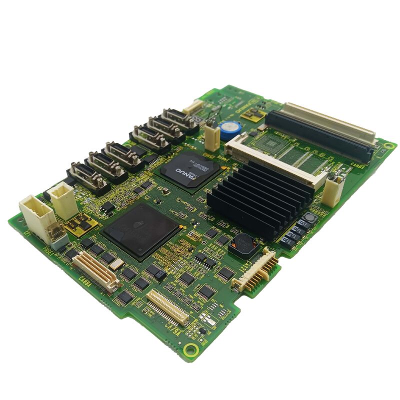
FANUC A20B-8200-0011 | Main CPU Graphic Display Control PCB — A20B-8200 Series, Master CNC Display Controller, Cross-Reference A350-8200-T018, Japan Origin
Overview
The FANUC A20B-8200-0011 is a board with a role that is easy to underestimate from its name — "graphic display control PCB" sounds secondary, but in a working CNC machine, a failed display is effectively a machine that cannot be operated.
The operator cannot see axis positions, cannot read alarm messages, cannot navigate programmes, cannot check spindle speed or feed override. Even if the servo system and PMC are fully functional, a machine with a blank or corrupted screen is down for production.
The A20B-8200-0011 is the master board in the display processing chain — the board that has both CPU capability (to process display data) and graphic control capability (to coordinate subordinate display modules).
In earlier FANUC CNC generations, graphic functions were typically handled by separate, dedicated graphic sub-boards with no CPU function of their own; the A20B-8200 generation represents FANUC's move toward more integrated display control hardware, placing CPU intelligence directly on the graphic display board itself.
The cross-reference number A350-8200-T018 appears in FANUC's parts documentation alongside the primary A20B-8200-0011 part number — these two numbers refer to the same physical board and are interchangeable when searching parts catalogues.
Having both reference numbers available simplifies parts sourcing because some FANUC documentation and parts systems use one designation while others use the other.
Key Specifications
| Parameter |
Value |
| Cross Reference |
A350-8200-T018 |
| Function |
Main CPU + Graphic Display Control |
| Architecture |
Master display controller (supervises sub-modules) |
| Series |
A20B-8200 |
| Status |
Available — refurbished, tested |
| Origin |
Japan |
What "Main CPU Graphic" Means in Practice
The description of this board as "Main CPU Graphic" refers to its dual-function design in FANUC's display architecture. In a FANUC CNC with multiple graphic processing boards, there is typically a hierarchy: the main graphic CPU board (like the A20B-8200-0011) receives high-level display data from the CNC's control processor, interprets which screen elements need to be rendered, and distributes rendering commands to the sub-graphic modules that handle specific portions of the display output.
This master-controller architecture serves a practical purpose.
The CNC's main control processor has enough to do managing servo loops, executing interpolation, scanning PMC ladder logic, and monitoring system status — offloading all display rendering to a dedicated display CPU means the control processor is not interrupted by display tasks.
The display CPU on the A20B-8200-0011 handles the continuous task of keeping the operator's screen refreshed with current data, independently of whether the main control CPU is busy.
When this board fails, the consequences depend on which of its functions fail first. If the CPU function fails, no data reaches the sub-graphic modules, resulting in a completely blank or static screen. If the graphic control function fails, the display may show scrambled data or only partial content.
Knowing which type of failure has occurred helps the maintenance engineer prioritise — a complete blank screen points directly to the A20B-8200-0011, while a partially corrupted display may indicate either this board or a sub-graphic module.
Display Fault Diagnosis — Isolating the A20B-8200-0011
Diagnosing a CNC display fault requires working through the signal chain from the CNC's main control processor down to the screen:
Step 1: Confirm whether the CNC's other functions are operational. If axes respond to jog commands (even without seeing the display), the spindle starts, and the PMC is executing machine functions, the control side is working — the fault is in the display chain.
Step 2: Check the display unit's power supply and backlight (for LCD screens). A screen that is dark but has a warm backlight is powered — if no image appears even with correct backlight power, the display electronics or the signal from the display board have failed.
Step 3: If a test screen or startup message would normally appear at power-on, and nothing appears, the A20B-8200-0011 has not initialised its display output. This is the pattern most likely to point to the main CPU graphic board.
Step 4: If some screen elements appear correctly (softkey labels, for example) but other areas are blank or corrupted, the sub-graphic module handling the affected display area may be the fault source rather than the main CPU graphic board.
No Data Loss with Display Board Replacement
One of the reassuring aspects of replacing the A20B-8200-0011 is that this board contains no machine-specific data. No parameters, no part programmes, no PMC ladder, no tool offsets are stored in the graphic display control board.
All of that data resides in the CNC's FROM and SRAM modules, which are on the main CPU board and are not affected by graphic board replacement.
Display board replacement is therefore among the cleanest maintenance procedures available — physically swap the board, apply power, and verify the display. No backup, no restore, no parameter verification sequence. Just confirm the screen shows correctly across the CNC's various display pages.
FAQ
Q1: The CNC operator panel has a completely blank screen at power-up, but the machine's axes respond normally to jog inputs from the keyboard. Does this confirm the A20B-8200-0011 has failed?
Operational axes despite a blank screen strongly supports a display subsystem fault rather than a main control board fault. Confirm the display unit itself is powered (check backlight indicator, measure display power supply voltage if accessible).
If the display unit is powered but no image appears, the display control board is the primary suspect. Before replacing, also check the cable connection between the display board and the display unit — a loose display cable produces the same symptom as a failed display board at zero cost.
Q2: Is the A20B-8200-0011 interchangeable with the adjacent variant A20B-8200-0010?
These two part numbers are close but distinct board variants within the A20B-8200 family. They may serve different CNC configurations or software revision levels.
Before substituting one for the other, confirm from FANUC's official cross-reference documentation that the -0010 and -0011 are listed as interchangeable for the specific CNC installation. Substituting an incompatible variant can result in display initialisation failure or incorrect screen rendering even with the replacement board fully functional.
Q3: The display shows correct CNC status screens but the graphic toolpath preview function shows a completely blank area. Is this the A20B-8200-0011?
Selective failure of only the graphic toolpath display while all character-mode screens (parameters, offsets, programme listing) are correct points to the graphic rendering function rather than the main CPU function — the CPU is communicating correctly but the graphic output is failing.
This pattern may indicate the sub-graphic module rather than the master A20B-8200-0011, depending on the specific display architecture.
The A20B-8200-0011 is still worth investigating if sub-module replacement does not resolve the fault.
Q4: How is the A20B-8200-0011 tested after replacement before returning the machine to production?
Navigate through each of the CNC's display pages systematically: POSITION, PROGRAMME, OFFSET/SETTING, SYSTEM parameters, MESSAGE/alarm history, GRAPH (toolpath simulation), and any machine-builder custom screens.
Verify that each page loads correctly, refreshes when data changes (change a parameter and verify the screen updates), and transitions smoothly when pages are switched. Test the MDI function to confirm keystrokes appear on screen.
A board that passes this comprehensive screen navigation check is unlikely to have any residual display faults.
Q5: Can the A20B-8200-0011 be repaired at component level after electrical damage?
Component-level repair is possible for FANUC-specialist repair centres with appropriate equipment. Common failure modes include power supply IC failure, input protection component damage, and in some cases oscillator or clock circuit failure.
A completely failed display CPU IC is typically not repairable at economic cost. Partial failures — where some display functions work and others do not — are often caused by specific peripheral ICs that can be replaced.
For production-critical machines where downtime cost is high, using a pre-tested exchange unit while the original is repaired is the most practical approach.

 Your message must be between 20-3,000 characters!