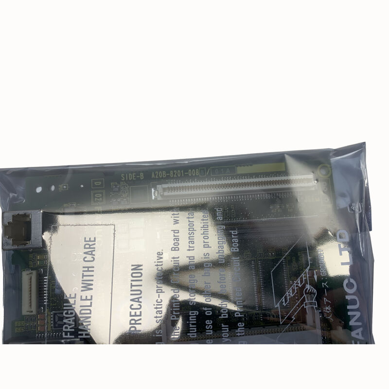
FANUC A20B-8201-0088 | 0i-D Mate Main PCB — A20B-8201 Series, Master Control Board for FANUC Series 0i-D Mate CNC Controllers, Japan Origin
Overview
The FANUC A20B-8201-0088 is the main PCB for the FANUC Series 0i-D Mate — a CNC generation that reflects a fundamental evolution in how FANUC packages its control intelligence.
The "Mate" designation carries real engineering meaning: it identifies the streamlined, cost-optimised variant of the 0i-D platform, designed specifically for machine tool configurations that need the full reliability and motion control accuracy of FANUC's i-series CNC without the full axis count and option depth of the flagship 0i-D.
The A20B-8201 board family represents FANUC's architectural shift to high-integration boards in the i-series generation.
Where the A16B-3200 family (main boards for Series 16/18/0i-B) accepted many separate plug-in DIMM modules for each functional area, the A20B-8201 generation integrates more functions directly on the board.
The main PCB carries onboard memory, the FSSB fibre-optic servo bus interface, the spindle serial interface, and the primary I/O connections — the A20B-8201-0088 for the 0i-D Mate represents this design philosophy applied to the compact Mate controller form factor.
FANUC's 0i-D series, launched in the late 2000s and remaining in active production well into the 2010s, brought a generation of improvements over the 0i-C: enhanced block processing speed, more advanced FSSB servo communication, improved high-speed cutting performance (especially for die and mould machining), and new safety functions.
The Mate variant made these capabilities available in a form suitable for the high-volume compact machine tool segment — the 2-axis CNC lathe, 3-axis machining centre, and specialised machine markets where Mate-class controls have always dominated in terms of global installed units.
Key Specifications
| Parameter |
Value |
| CNC Series |
0i-D Mate |
| Architecture |
High-integration main board |
| Servo Bus |
FSSB (Fibre-optic Serial Servo Bus) |
| Series |
A20B-8201 |
| Form Factor |
Integrated LCD-mount or stand-alone |
| Origin |
Japan |
0i-D Mate vs Full 0i-D — Understanding the Difference for Maintenance
The 0i-D Mate and the full 0i-D share the same CNC generation and many of the same software capabilities, but the hardware configurations differ in ways that matter for spare parts management.
The main board for the full 0i-D (represented by boards like the A20B-8200-0841 and related variants) is a different physical board with different connector arrangements and different expansion capacity than the A20B-8201-0088 used in the Mate.
The A20B-8201 Mate board is physically smaller and carries fewer interface connectors than the full 0i-D main board — this is appropriate for the Mate's limited axis count (typically 2–3 controlled axes versus the full 0i-D's higher limit) and simplified I/O configuration.
These boards are not interchangeable; installing a full 0i-D main board in a Mate controller's rack or panel mount is not physically possible without mechanical modification, and the software configuration (option registrations, axis count limits) would need to match the original anyway.
When sourcing a replacement A20B-8201-0088, confirm the part number precisely — other A20B-8201 variants (the -0081, -0083, -0212, and others) serve different 0i-D configurations and robot controllers and will not function as substitutes.
What Is Stored on the A20B-8201-0088 and What Is Not
A common question during main board replacement concerns data retention. On the 0i-D Mate, the board itself carries some fixed hardware resources, but the machine-specific data — parameters, part programmes, PMC ladder, tool offsets — lives in FROM and SRAM modules or in flash memory areas that are sometimes integrated into the main board or in separate plug-in cards, depending on the specific 0i-D Mate hardware configuration.
Before replacing the A20B-8201-0088, back up everything: all CNC parameters via the I/O function, the PMC ladder via the PMC parameter I/O function, all part programmes via the programme list I/O, and work coordinate and tool offset data via the offset I/O.
The 0i-D Mate supports memory card (CF card), USB memory, and RS-232C as I/O media depending on the installed options.
After replacement, all backed-up data must be reloaded and the system must be verified for correct axis movement, spindle function, and PMC I/O operation before the machine returns to production.
FSSB — What It Means for the 0i-D Mate System
One of the most significant changes from earlier FANUC CNC generations to the 0i-D is the universal use of FSSB (FANUC Serial Servo Bus) for servo amplifier communication.
Where earlier controls used either analogue ±10V signals or PWM-type commands to talk to servo amplifiers, the 0i-D uses a fibre-optic serial bus — a dedicated high-speed communication link between the main PCB and the servo amplifiers, carrying position commands, speed commands, and feedback data in a synchronous digital format with very low latency.
On the A20B-8201-0088 board, the FSSB interface circuitry is integrated — the fibre-optic connectors and the FSSB communication controller chips are built into the main board, not on a separate axis control card as in earlier generations.
This means an FSSB-related fault that would previously have been isolated to a removable axis card now requires the main board to be diagnosed or replaced if the FSSB hardware itself has failed.
FAQ
Q1: What backup procedures are mandatory before replacing the A20B-8201-0088?
Back up all CNC parameters (SRAM data), part programmes, PMC ladder, and offset tables to external media before the board is removed.
On the 0i-D Mate, these are accessed through the MDI → SYSTEM → INPUT/OUTPUT menus.
If the board has failed in a way that prevents the CNC from booting normally, parameters must be retrieved from the most recent external backup.
Facilities without a current backup face parameter re-entry from the machine's acceptance documentation — a time-consuming process that underscores the importance of maintaining scheduled parameter backups as part of routine maintenance.
Q2: The CNC shows a system alarm during boot that prevents reaching the normal operating screen. Can the board be determined as faulty from this symptom?
A startup system alarm (PS alarm, SV alarm during boot, or display of a CNC error screen with no axis movement possible) can result from a main board fault, a failed servo amplifier, an SRAM data corruption, or an FSSB communication problem.
Before concluding the main board has failed, check the diagnostic LED array on the board's face — each LED represents a specific subsystem's status, and the combination of lit/unlit LEDs during a failed boot identifies which subsystem has not initialised.
The 0i-D Mate maintenance manual provides the LED diagnostic table. Only after LED diagnostics and confirming that power supply voltages are correct should board replacement be considered as the next step.
Q3: Does the 0i-D Mate Mate version support the same software options as the full 0i-D?
The software option set available on the 0i-D Mate is a subset of the full 0i-D's option menu.
Options that require more than the Mate's base axis count or hardware resources — such as 5-axis simultaneous machining, additional path control, or high-performance AI contour control — are not available on the Mate.
The options that are registered on the A20B-8201-0088 board (stored in the board's FROM area or via FANUC's option registration system) are specific to the original machine's purchased configuration.
A replacement board must either have the same options registered or be configured to match through FANUC's option key registration process.
Q4: How does the FSSB connection fail, and what are the symptoms when it does?
FSSB failure on the 0i-D Mate typically presents as servo axis faults that appear immediately on power-up, before any axis movement is attempted — the servo amplifiers cannot establish their communication link with the main board.
Common FSSB failure causes include: physical damage to the fibre-optic cable (cracked, bent, or contaminated at the connector end), a failed FSSB transceiver on the main board or the amplifier, or a failed FSSB communication IC on the main board.
FSSB cable replacement is the first diagnostic step — these cables are consumable items that can be purchased separately.
If cable replacement does not restore FSSB communication, the main board or the servo amplifier's FSSB interface requires further investigation.
Q5: Is the A20B-8201-0088 repairable after failure caused by a power surge?
A power surge severe enough to damage the main board typically damages the input protection circuits first (TVS diodes, MOVs) and may also damage voltage regulator ICs or the FSSB communication chips.
Specialist FANUC repair centres with access to 0i-D test rigs can often repair surge-damaged boards by replacing the affected protection and communication components, restoring the board to full function.
The cost of repair versus the cost of a replacement board depends on the extent of damage — boards with burned PCB traces or failed embedded processors are generally not economically repairable, while boards with localised protection component damage are frequently restored successfully.

 Your message must be between 20-3,000 characters!