FANUC A20B-9000-0500 | Spindle Motor Encoder Board — Speed and Position Feedback for FANUC CNC Spindle Systems
What This Board Does — and Why It Must Work
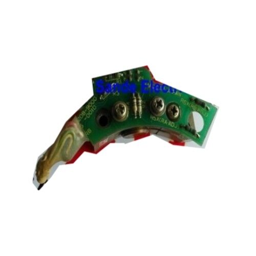
The A20B-9000-0500 is a spindle motor encoder board from FANUC's A20B-9000 family — the sensing PCB that mounts to the rear of the spindle motor and continuously measures shaft rotation. The spindle amplifier uses this feedback to hold commanded RPM against cutting load changes, thermal drift, and supply variation. This is the closed-loop function that gives FANUC spindle drives their speed stability under varying chip loads.
The position feedback role is equally important. Operations like rigid tapping, thread cutting, and spindle orientation all require the CNC to know where the spindle is within one revolution at any instant. Rigid tapping specifically demands real-time phase synchronisation between spindle rotation and Z-axis feed — the encoder provides the angular reference that makes accurate thread pitch possible. Without it, the CNC issues a spindle feedback alarm and refuses to execute the programme.
The board consists of a sensing PCB (stator element) and a rotor disc or target that mounts on the shaft extension. The PCB detects target rotation and generates feedback pulses. Rotor alignment at installation is critical — eccentricity in rotor mounting produces noise in the feedback signal that shows up as speed hunting or intermittent irregularities rather than a clean alarm.
A20B-9000 Series — Suffix Matching Required
The A20B-9000 family covers multiple spindle encoder board variants for different FANUC spindle motor types. The -0500 variant is matched to specific motor models within its generation. Adjacent variants — -0380, -0300, -0010 — share the same mounting concept but differ in sensing geometry, pulse output, and electrical interface.
Fitting the wrong variant produces incorrect speed readings or spindle alarms even if the unit powers on without fault. Always confirm the variant against the spindle motor's nameplate or the machine's parts list before ordering.
Diagnose the Cable First
Encoder cable and connector failures produce symptoms identical to a failed encoder board: spindle alarms, speed hunting, loss of orientation. Before replacing the A20B-9000-0500, inspect the encoder cable connector at the spindle amplifier end for corrosion, bent pins, and coolant residue. Check cable continuity — particularly for intermittent opens in shielded conductors near the motor end where flexing and heat cycling cause fatigue. Most "encoder faults" that do not involve the board itself are resolved at the cable or connector.
Key Specifications
| Parameter |
Value |
| Part Number |
A20B-9000-0500 |
| Series |
A20B-9000 |
| Type |
Spindle motor encoder board |
| Location |
Rear of spindle motor, under fan assembly |
| Connection |
Spindle amplifier (JY2 or equivalent) |
| Origin |
Japan |
FAQ
Q1: What are the main symptoms of a failing A20B-9000-0500?
Four recognisable patterns: (1) Spindle feedback alarm at power-up or during acceleration — the most direct indication. (2) Speed hunting at constant RPM — noisy or intermittent signal from a damaged rotor disc or loose mounting. (3) Rigid tapping producing inaccurate thread pitch — systematic pitch errors point to counting errors in the encoder even when no alarm has triggered. (4) Complete spindle refusal — the CNC will not execute spindle commands at all. In all cases, verify the encoder cable and connector before ordering the board.
Q2: Can the A20B-9000-0500 be repaired at component level?
Component-level repair is practiced by specialist CNC repair companies. The sensing PCB can suffer failures in the detection circuit, signal conditioning, or output driver stage — all repairable in principle. However, repair must include dynamic testing at actual operating speeds with a connected motor, not just a static bench test. A subtle counting error after repair causes real quality problems in the machine's output without generating a hard alarm.
Q3: How do I confirm the encoder board has failed rather than the cable?
Inspect the cable connector at the spindle amplifier for corrosion and damage. Check cable continuity. If the alarm persists with a confirmed-good substitute cable, the encoder board has almost certainly failed. On some FANUC controls, the diagnostics page shows raw encoder feedback data — absent or erratic data with a good cable connected confirms board failure.
Q4: Is the A20B-9000-0500 compatible with both older 0-series and newer 16i/18i/0i controls?
Compatibility is determined by the spindle motor and amplifier, not by the CNC control series. The encoder interfaces with the spindle amplifier — if the amplifier and motor are unchanged, replacing the A20B-9000-0500 with an identical unit restores normal function regardless of which CNC generation sits upstream. Compatibility questions arise when a machine has been re-controlled or when the spindle amplifier has been changed to a different generation.
Q5: Different A20B-9000 variants look physically similar. How is the correct one identified?
Each suffix identifies the design matched to a specific spindle motor type or generation. The -0500, -0380, -0300, and -0010 variants are not interchangeable — using the wrong one produces incorrect speed data or alarms even if physical fitment works. Confirm the exact variant from the motor nameplate or the machine's original parts documentation. Physical fitment is not a reliable compatibility indicator for this family.

 Your message must be between 20-3,000 characters!