FANUC A20B-9001-0480 | 52/40 Sink Type Sub I/O PCB — Piggyback I/O Expansion for FANUC Series 16/18 CNC, Extends DI/DO Capacity, Industrial Spare Part
Overview
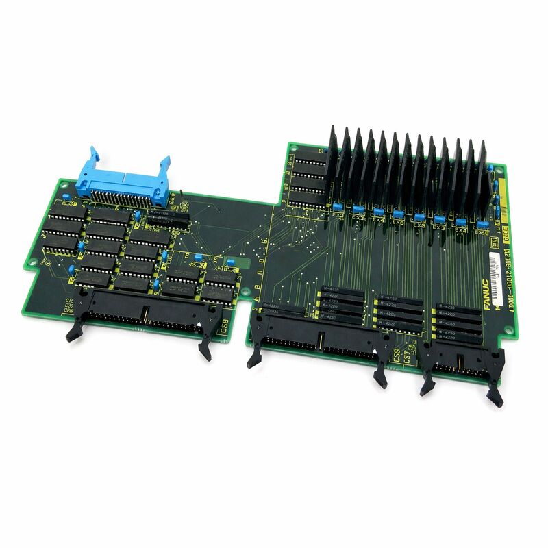
The FANUC A20B-9001-0480 occupies a very specific and practical role in the FANUC Series 16/18 CNC's I/O architecture: it gives a machine more signal connections without requiring a separate standalone I/O card or a second controller.
The sub I/O board piggybacks directly onto an existing primary I/O board, sharing the primary board's bus connection to the CNC while adding its own signal terminals.
The result is a compact, cost-effective I/O expansion that machine tool builders incorporated when a single primary I/O board's capacity was insufficient for a machine's full complement of inputs and outputs.
Understanding why I/O expansion is sometimes necessary requires knowing how machine tool I/O is distributed.
The PMC (Programmable Machine Controller) in a FANUC CNC executes the machine-specific ladder logic that controls every machine function except the actual axis and spindle motion — ATC tool selection and clamping, pallet changing, coolant on/off, chip conveyor, door interlocks, lubrication system, workpiece clamping, tailstock positioning, steady rests, hydraulic valve actuation, and countless other functions.
Each of these functions generates and consumes I/O signals: a door has an open limit and a closed limit (2 inputs), a hydraulic clamp has a solenoid command (1 output) and confirmed/unclamped limit switches (2 inputs), a tool magazine may have a signal for each magazine position sensor (as many as 60+ inputs on large magazines). Add these up across a fully equipped machining centre and the total I/O count easily exceeds what a single 104/80 board provides.
Key Specifications
| Parameter |
Value |
| Digital Inputs (DI) |
52 |
| Digital Outputs (DO) |
40 |
| Output Type |
Sink type (NPN, active-low) |
| Mounting |
Piggyback on primary I/O board |
| System Compatibility |
FANUC Series 16, 18 CNC |
| Combined DI/DO with Primary |
156 DI / 120 DO (with A16B-2202-0960 base) |
| Origin |
Japan |
The Sink Type Output — What It Means for Machine Wiring
"Sink type" in FANUC's I/O terminology means the output transistors pull the output terminal down to the 0V common rail when active (logic 1).
The external device — a solenoid valve, a relay coil, an indicator lamp — is connected between the positive supply rail (+24VDC) and the output terminal. When the PMC ladder activates the output, current flows from +24V through the device and into the output terminal, where the sink transistor passes it to 0V.
This sink (NPN) topology is widely used in Asian CNC machine tools and Japanese industrial equipment. Most solenoid valves, relays, and pilot lamps designed for FANUC-compatible systems connect between 24VDC and the sink output without any additional components.
The machine wiring diagram for the specific machine tool shows which output addresses correspond to which physical output terminals on the I/O board's connectors, and which external devices are wired to each terminal.
The A20B-9001-0480's 40 sink outputs follow the same electrical characteristics as the primary I/O board's outputs — designed for the 24VDC machine tool control voltage standard and capable of handling the inductive loads (solenoid valve coils, relay coils) that are standard in machine tool electrical systems.
Installation Position and the Primary I/O Board Relationship
In the FANUC Series 16/18 CNC rack, the primary I/O board occupies a designated slot.
The A20B-9001-0480 sub I/O board connects directly to the primary board through a dedicated expansion connector — it does not occupy an independent rack slot but rides on the primary board, using that board's rack connection to communicate with the CNC's PMC.
The PMC ladder programme accesses the sub I/O board's inputs and outputs through specific G-address (outputs from PMC) and F-address (inputs to PMC) ranges that are assigned to the sub board's signals in the I/O board's address mapping.
The machine tool builder defines this address mapping in the PMC parameters when the machine is built — the A20B-9001-0480's signals appear to the PMC ladder as additional DI/DO addresses beyond those of the primary board.
When replacing the A20B-9001-0480, the replacement board's physical installation is the reverse of the above: connect it to the primary board's expansion connector, secure it mechanically (the board is typically secured to the primary board's bracket or standoffs), reconnect the I/O wiring to the sub board's terminal strips or connector, and verify PMC I/O address operation by checking signals on the PMC diagnose screen.
PMC Diagnose Screen — First Tool for Fault Isolation
When a signal originating from the A20B-9001-0480 is suspected of failing — a machine function not responding to a command, an input not reflecting the physical sensor state — the first diagnostic step is the CNC's PMC diagnose screen.
Accessible through the MDI panel, the diagnose screen shows the real-time state of every PMC address, including the G-addresses (commanded outputs) and F-addresses (received inputs) corresponding to the sub board's signals.
If a commanded output is active (G-address bit = 1) but the physical output terminal does not show 24V when measured with a multimeter, the fault is either in the output transistor on the sub board, in the wiring from the terminal to the device, or in the device itself.
If an input address (F-address bit) does not reflect the physical sensor state (sensor activated but bit = 0, or sensor inactive but bit = 1), the fault is in the input circuit on the sub board, the input wiring, or the sensor.
This systematic signal-tracing approach quickly isolates whether the A20B-9001-0480 itself has failed or whether the fault is in the external wiring and devices connected to it.
FAQ
Q1: Is the A20B-9001-0480 always present, or is it an optional addition to the Series 16/18 I/O system?
It is an optional addition — the primary I/O board operates independently, and the A20B-9001-0480 is only installed when the machine tool builder determined that the primary board's 104/80 DI/DO capacity is insufficient for the machine's I/O requirements.
Some Series 16/18 machines have the sub board installed from the factory; others do not.
Whether the sub board is present in a specific machine is confirmed by physically inspecting the I/O board assembly or by referencing the machine's electrical documentation.
A machine running without its sub board installed when the PMC ladder expects it will show alarms or incorrect I/O behaviour for any addresses assigned to the sub board.
Q2: After replacing the A20B-9001-0480, some of the machine's functions are still not working. What should be checked?
Verify that the replacement board is correctly seated and connected to the primary I/O board's expansion connector — a partial connection causes some signals to work and others to fail. Then check all wiring reconnections at the sub board's I/O terminals.
Use the PMC diagnose screen to confirm which specific input and output addresses are showing incorrect states, then trace those specific signals through the wiring from the terminal to the device.
A systematic address-by-address check against the machine's I/O list (normally in the machine's electrical documentation) confirms whether the problem is board-internal or wiring-external.
Q3: Can the A20B-9001-0480 be used with FANUC Series 0 or 21 CNC systems?
The A20B-9001-0480 is specified for FANUC Series 16/18 CNC systems. Its compatibility with other FANUC CNC generations (Series 0, 21, 0i) depends on whether those systems' primary I/O boards have the same expansion connector and whether the PMC address mapping is compatible. Do not assume cross-generation compatibility — confirm against the specific machine's hardware documentation and the CNC generation's hardware manual before ordering or installing.
Q4: The sub I/O board has "sink type" outputs. Can source-type (PNP) devices be connected to these outputs?
Sink type outputs are designed for current-sinking operation with 24VDC positive supply loads (solenoid valve coils, relay coils connected to +24V). Source type (PNP) sensors or other source-type devices cannot directly replace or connect to sink-type output terminals without a relay or interface circuit.
When connecting field devices, verify that the device's wiring topology (load connected to +V or load connected to 0V) matches the output type (sink or source).
For input channels, similar considerations apply — the A20B-9001-0480's input circuits are designed for specific input signal voltage and topology as documented in the Series 16/18 connection manual.
Q5: Is there any CNC data stored in the A20B-9001-0480 that needs backing up before replacement?
No. The A20B-9001-0480 is a purely electrical signal interface board — it contains I/O transistors, input optocouplers, signal conditioning circuits, and the physical connectors for field wiring, but stores no machine parameters, PMC ladder programmes, or configuration data.
All PMC data resides in the CNC controller's FROM/SRAM memory modules, unaffected by I/O board replacement. No data backup is required specifically for replacing this board.

 Your message must be between 20-3,000 characters!