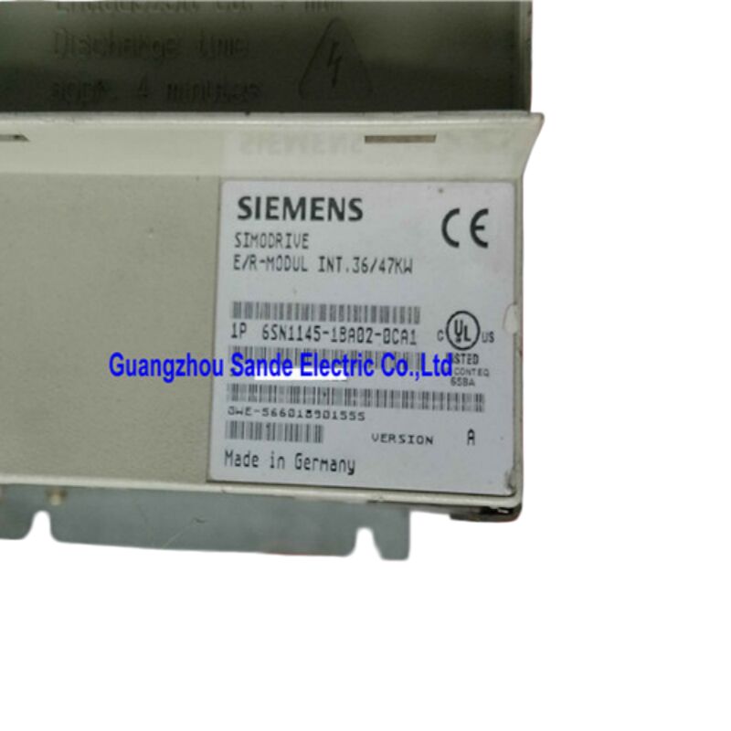
Siemens 6SN1145-1BA02-0CA0 — SIMODRIVE 611 Infeed / Regenerative Feedback Module, 36/47 kW, Closed-Loop Control
A Different Kind of Power Module
Most infeed modules for servo drive systems do one thing: take power from the mains and feed it to the DC bus. The 6SN1145-1BA02-0CA0 does something considerably more sophisticated. As a regulated infeed / regenerative feedback (I/R) module in the SIMODRIVE 611 platform, it not only supplies the DC bus — it actively controls the bus voltage through closed-loop regulation, and when connected axes decelerate, it recovers the resulting kinetic energy and pushes it back to the mains supply rather than burning it off in a resistor.
That distinction matters in real production environments. It means lower energy consumption across an entire machining cycle, a cleaner and more stable DC bus for all connected drives, and the elimination of braking resistors from the cabinet design. For multi-axis machine tools running frequent acceleration/deceleration cycles — a five-axis machining center mid-program, for instance, or a high-speed grinding machine cycling between parts — the energy recovery function translates into measurable electricity cost reduction over time.
Technical Specifications
| Parameter |
Value |
| Part Number |
6SN1145-1BA02-0CA0 |
| Series Compatibility |
SIMODRIVE 611A / 611D |
| Module Type |
I/R Infeed / Regenerative Feedback Module |
| Control Type |
Closed-loop (regulated) |
| Power Rating — Continuous |
36 kW |
| Power Rating — Peak |
47 kW |
| Input Voltage |
380–480 V AC, 3-phase, ±10% |
| Input Frequency |
50 / 60 Hz |
| DC Bus Voltage |
Approx. 600–625 V DC (regulated) |
| Rated Output Current |
Approx. 67 A |
| Cooling Method |
Internal heat dissipation |
| Mains Contactor |
Integrated, with break contact (NC) |
| Operating Temperature |
0°C to +45°C |
| Storage Temperature |
−20°C to +45°C |
| Dimensions (W × H × D) |
Approx. 203 × 457 × 279 mm |
| Weight |
Approx. 5.96–15.5 kg |
| Protection Class |
IP00 (panel-mount, cabinet installation) |
| Platform Status |
Discontinued / Spare part |
The I/R Module vs. the Unregulated UI Module — Why It Matters
If you're specifying a replacement or comparing options within the SIMODRIVE 611 range, understanding this distinction saves time and avoids specification errors.
The unregulated (UI) infeed module — such as the 6SN1145-1AA00-0CA0 — produces a DC bus voltage proportional to the incoming mains voltage. It rectifies the supply passively, and during axis deceleration, regenerated energy has nowhere to go except into an external braking resistor. The simplicity of the circuit is an advantage in terms of cost and robustness, but it places thermal demands on the resistor and wastes the regenerated energy.
The I/R module (this product) uses active switching and closed-loop voltage regulation to maintain a stable DC bus regardless of load changes or minor mains fluctuations. Crucially, when regenerative energy appears on the bus — from a decelerating axis — the module's IGBT bridge can reverse the current flow and feed that energy back into the three-phase supply. No braking resistor is required for normal deceleration cycles. The cabinet runs cooler, energy waste is minimized, and the DC bus voltage remains more consistent under dynamic load conditions.
For applications with frequent braking, high-inertia loads, or multiple axes cycling at different phases of their motion profiles, the I/R module is the appropriate engineering choice.
Closed-Loop Control: What the Regulation Actually Does
The "closed-loop control" descriptor in the product description refers specifically to DC link voltage regulation — not to motor control, which happens in the individual axis power modules. The 6SN1145-1BA02-0CA0 continuously monitors the DC bus voltage and adjusts its switching pattern to hold it at the target value of approximately 600–625 V DC.
In practice, this regulated behavior has several benefits for the connected drive group:
The bus voltage stays within a narrow band even when multiple axes simultaneously accelerate, which would otherwise cause a bus voltage dip. Conversely, simultaneous braking of several axes doesn't produce an overvoltage spike. Axis drive modules operating from a stable regulated bus deliver more predictable torque response, particularly at high speeds where the margin between motor back-EMF and available bus voltage becomes tight. For precision applications — cylindrical grinding, gear profile machining, precision boring — this voltage stability has a direct effect on the consistency of servo response.
Integrated Mains Contactor with Break Contact
One feature that distinguishes the 6SN1145-1BA02-0CA0 from some other variants in the SIMODRIVE 611 infeed range is its integrated mains contactor with NC (normally closed) break contact.
This built-in contactor serves as the main switching element between the three-phase supply and the infeed rectifier. When the machine is powered on in the correct sequence, the SIMODRIVE 611 system closes this contactor under controlled conditions — limiting inrush current and ensuring the DC bus charges gradually rather than through an uncontrolled step. The NC break contact provides a feedback signal to the control system confirming contactor state, which is used in the machine's ready-to-run logic and in fault detection.
Integrating the contactor into the module simplifies cabinet design: there is no separate external contactor required for the mains connection. This reduces wiring complexity, saves panel space, and eliminates one more potential source of fault in the power-up sequence.
Internal Cooling — Cabinet Design Implications
The "0CA0" suffix in this part number specifies internal heat dissipation — the module dissipates its operating losses into the cabinet interior air rather than through an external heatsink protruding through the rear panel.
This configuration suits installations where the control cabinet cannot be modified for rear-panel pass-through cooling, or where the machine enclosure design doesn't permit external heatsink access. The trade-off is that the cabinet must be sized and ventilated adequately. At 36–47 kW throughput, this module generates meaningful thermal load alongside the connected axis power modules.
Cabinet design for internally cooled SIMODRIVE 611 groups typically requires forced-air ventilation calculated against the total power dissipation of all installed modules. Insufficient ventilation leads to thermal derating and eventual fault trips — symptoms that can be misattributed to drive faults if the cabinet cooling system isn't examined first.
System Placement and Drive Group Configuration
Within a SIMODRIVE 611 drive group, the infeed module always occupies the leftmost position on the module rail. To its right sits the NCU box (if a SINUMERIK numerical control is used), followed by spindle drive modules in descending current order, then feed axis power modules arranged similarly.
The 6SN1145-1BA02-0CA0 connects to the shared DC bus through the module backplane — no separate high-current wiring between adjacent modules is required. The total DC bus load from all connected power modules must not exceed the infeed module's rated peak capability of 47 kW, accounting for duty cycle, coincidence factor, and application-specific loading. Overshooting this limit triggers infeed overcurrent protection, which can be confusing to diagnose if the system wasn't properly sized at installation.
The module requires a correctly specified HF commutating reactor and line filter upstream. For mains supplies other than a standard TN grounded system, an isolation transformer with the Yyn0 vector group is also mandatory. These requirements are not optional — they protect the rectifier bridge and ensure EMC compliance.
Typical Machine Applications
The 36/47 kW rating of this module positions it in the mid-to-upper range of the SIMODRIVE 611 infeed family — large enough to support demanding multi-axis configurations, compact enough for standard control cabinet designs. It is routinely found in:
- Multi-axis CNC machining centers with high-power spindle drives and three or more feed axes
- 5-axis and compound machining centers where simultaneous multi-axis motion demands a stable DC bus
- CNC grinding machines running high-cycle-rate programs with frequent deceleration events
- Turning and milling centers with large C-axis or driven tooling configurations
- Gear hobbing and profile grinding machines requiring precise torque regulation
The dual compatibility with both SIMODRIVE 611A (analog control) and SIMODRIVE 611D (digital control) systems makes this module useful across a wide installed base of machine tools — particularly relevant when a machine has undergone a partial control upgrade.
Procurement Reality for a Discontinued Module
The SIMODRIVE 611 platform has reached end-of-active-manufacturing status at Siemens, transitioning to the SINAMICS S120 family for new installations. The 6SN1145-1BA02-0CA0 carries discontinued / spare part classification, meaning factory-new stock cannot be guaranteed through standard channels.
For maintenance applications, three practical procurement routes exist. New-old-stock units offer the highest confidence in component condition but command a significant price premium and availability cannot be guaranteed. Professionally refurbished or exchange units from reputable CNC specialist suppliers — those who test on live drive test benches under load, not just power-on checks — offer a cost-effective alternative with meaningful quality assurance. Repair of a failed original unit is viable when the damage is limited to identifiable component failures; quality repair houses will replace capacitors and other age-sensitive components proactively, not just the visibly failed parts.
Given the critical role of the infeed module in the entire drive group, sourcing a tested spare for stock is prudent maintenance practice on any machine where this module is installed.
Frequently Asked Questions
Q1: What is the functional difference between the 6SN1145-1BA02-0CA0 and the 6SN1145-1AA00-0CA0 unregulated infeed module?
The core difference lies in how each module handles the DC bus voltage and what happens to regenerative energy. The 6SN1145-1AA00-0CA0 is an unregulated (UI) module — it passively rectifies the mains supply, and the DC bus voltage fluctuates with mains and load changes. Regenerative energy from braking axes must be dissipated through an external braking resistor. The 6SN1145-1BA02-0CA0, by contrast, uses active closed-loop regulation to hold the DC bus at a consistent 600–625 V DC, and its IGBT-based inverter stage can return regenerative braking energy to the mains supply. This eliminates the need for braking resistors in most applications and reduces cabinet thermal load. For machines with frequent or high-energy braking cycles, the I/R module is the correct choice.
Q2: Does the integrated mains contactor in the 6SN1145-1BA02-0CA0 replace the need for an external line contactor?
Yes, for the infeed connection. The integrated mains contactor handles the controlled switching of the three-phase supply to the module's rectifier bridge, including soft charge sequencing of the DC bus capacitors. The NC break contact provides a status signal to the machine control for interlocking. There is no need to fit a separate external mains contactor for the SIMODRIVE 611 drive group when using this module. However, upstream protective devices — line fusing, a circuit breaker, the HF commutating reactor, and a line filter — are still required separately and must be correctly rated for the module's maximum input current.
Q3: Can this module operate on a 480 V supply as well as a 400 V supply?
Yes. The input voltage range of 380–480 V AC (±10%) covers both common industrial supply standards. On a 400 V nominal supply the DC bus settles at approximately 600 V DC; on a 480 V nominal supply the regulated output holds to approximately 625 V DC. The ±10% tolerance accommodates typical supply voltage variations without affecting module performance. For supply voltages outside the 380–480 V range — such as 200 V, 220 V, or 575 V systems — an appropriately rated matching transformer is required, as specified in the SIMODRIVE 611 configuration documentation.
Q4: Are the CA0, CA1, and CA2 hardware revisions of this module fully interchangeable for replacement purposes?
In the vast majority of maintenance situations, yes. The CA0, CA1, and CA2 suffixes indicate sequential hardware revision levels within the same product. Electrical ratings, physical dimensions, connector positions, and system interface behavior are consistent across all three revisions. When replacing a failed CA0 with a CA1 or CA2 unit, no parameter changes or reconfiguration are typically required. The main exception to be aware of is firmware compatibility on very early SIMODRIVE 611A systems, where a very late hardware revision may require a minimum control firmware version. If the machine's control software is current, this edge case rarely applies.
Q5: The machine keeps tripping with a DC bus overvoltage fault during deceleration — could the infeed module be failing?
Possibly, but this symptom has several potential causes that should be ruled out before condemning the module. First, confirm that the module's regenerative feedback function is properly enabled in the system configuration — on some machines, a parameter or hardware setting can disable regenerative feedback mode, reverting the system to unregulated behavior. Second, check whether the total connected axis load during the deceleration event exceeds the module's peak 47 kW regenerative capability; in heavily loaded systems, simultaneous braking of multiple high-power axes can overwhelm any infeed module. Third, inspect the mains supply at the moment of fault — a high-impedance supply connection or a faulty commutating reactor can prevent proper energy return. If all these factors check out and the fault persists, the module's IGBT bridge or feedback control circuit may have degraded, and professional testing on a drive test bench is the next step.
The 6SN1145-1BA02-0CA0 is a cabinet-mounted industrial power module rated IP00. It must be installed in an adequately enclosed and ventilated control cabinet. A correctly specified HF commutating reactor and line filter are required upstream. All installation, commissioning, and replacement work must be performed by qualified personnel following applicable electrical safety procedures and the relevant SIMODRIVE 611 system documentation.


 Your message must be between 20-3,000 characters!
 English