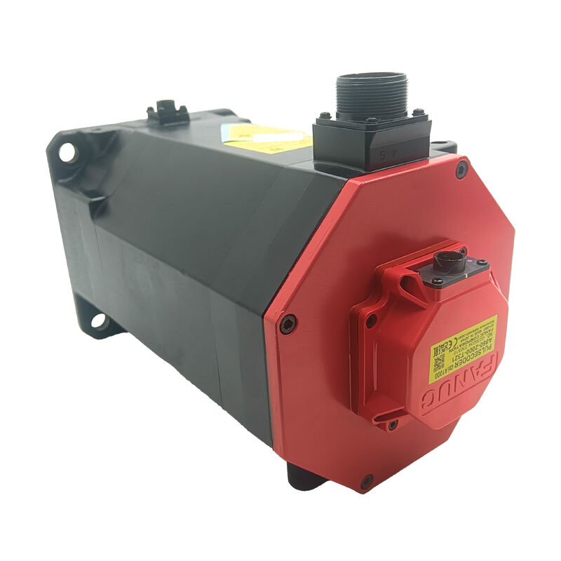
FANUC A06B-0249-B400 | αiF 22/3000 HV AC Servo Motor — 22 Nm / 4 kW / 3000 rpm / 400V / Smooth Shaft / 24V Brake
AiF22/3000 HV — The High-Voltage Distinction
The HV designation in the αiF 22/3000 HV identifies this motor as a 400V-class unit — distinct from the standard αiF 22/3000 (200V-class) that operates from a 200–230V AC servo amplifier system. High-voltage servo systems deliver the same mechanical performance (22 Nm, 4 kW, 3000 rpm) at lower current for equivalent power, which reduces the cross-section of motor power cabling and the current demand on the servo amplifier's input power stage. The 400V-input servo amplifier configuration is required — this motor is not compatible with standard 200V Alpha i servo amplifiers.
At 22 Nm continuous torque and 4 kW, the αiF 22/3000 HV is sized for primary feed axis drives on CNC machining centres and turning centres where sustained torque at 3000 rpm maximum speed is required. The αiF (F-series) designation indicates FANUC's full-inertia motor class — higher rotor inertia than the αiS (S-series) low-inertia motors, providing the load absorption characteristics suited to mid-to-heavy axis drives.
Key Specifications
| Parameter |
Value |
| Rated Torque |
22 Nm |
| Rated Output |
4 kW |
| Rated Speed |
3,000 rpm |
| Rated Voltage |
400V (HV) |
| Back-EMF |
84V |
| Peak Current |
40 A |
| Encoder |
αiA 1000 absolute |
| Shaft |
Smooth (SLK, no keyway) |
| Brake |
24V DC spring-applied |
| IP |
IP65 |
| Weight |
18 kg |
B400 Suffix — Smooth Shaft and 24V Brake
The B400 part suffix identifies two configuration elements:
- SLK smooth shaft (no keyway): torque is transmitted through friction clamping at the coupling hub, not through a keyed interlock
- 24V DC spring-applied brake: the brake engages mechanically when the 24V supply is removed — holding the axis at rest when the servo is de-energised, at E-stop, and at power loss
The spring-applied brake is the appropriate specification for vertical axes, inclined axes, and gravity-loaded mechanisms where the axis must be held mechanically when servo control is not active. When the brake receives 24V DC, it releases and the axis moves normally. When 24V is removed, spring force clamps the brake. This fail-safe characteristic ensures the axis is held mechanically in the event of a power or control failure.
SLK shaft note: The smooth shaft requires correct coupling hub installation torque at commissioning and periodic re-inspection in service. Friction-clamped hubs can develop micro-slip under sustained reversing torque loads if the clamping force has relaxed.
αiA 1000 Encoder — Absolute Position
The αiA 1000 absolute pulsecoder provides 1000 ppr resolution and retains absolute shaft position through power-off cycles via backup battery at the servo amplifier. At power-on, axis position is immediately known without a reference-return cycle. The backup battery is in the servo amplifier, not in the motor — monitor the amplifier's battery alarm indicator and replace per FANUC's replacement schedule before the alarm activates, to avoid absolute position data loss during the swap.
FAQ
Q1: What amplifiers are compatible with the A06B-0249-B400?
The αiF 22/3000 HV is a 400V-class motor requiring HV-rated Alpha i servo amplifiers. Confirm the specific amplifier model from the machine's original parts documentation — using a 200V-class amplifier with a 400V-class HV motor is not compatible. The motor type parameter in the CNC must also be set for the αiF 22/3000 HV specification.
Q2: The suffix is B400 — what does each character indicate?
In FANUC's Alpha i motor nomenclature, the B-series suffix encodes shaft and brake configuration. The B400 indicates a straight smooth shaft (SLK, no keyway) with a 24V DC spring-applied brake. B100 would be straight smooth shaft without brake; B175 would be taper shaft without brake. Confirm the full suffix from the installed motor's nameplate before ordering — shaft and brake configuration must match.
Q3: The brake requires 24V DC to release. What happens during an E-stop?
When the E-stop circuit removes the 24V brake supply, the spring-applied brake engages mechanically and holds the axis. This is the intended fail-safe behaviour — on E-stop or any power interruption, gravity-loaded axes are held mechanically without relying on servo control. Ensure the machine's brake circuit wiring and the E-stop logic are correctly configured to remove brake voltage at E-stop.
Q4: The αiA 1000 encoder is absolute. Where is the backup battery located?
The absolute position backup battery is in the servo amplifier, not in the motor. Monitor the amplifier's battery alarm indicator. When the alarm activates, replace the battery with the amplifier powered on to maintain position data during the swap. A depleted battery resets the absolute counter — the axis loses its position reference and requires a reference return before production resumes.
Q5: What should be checked on a used A06B-0249-B400?
Verify the 24V brake engages and releases correctly at the rated supply voltage. Measure three-phase winding resistance for balance and insulation resistance to earth with the encoder cable disconnected. Inspect the smooth shaft for fretting marks from prior coupling installation. Check the brake for oil contamination that reduces the braking torque. At 18 kg, confirm appropriate mechanical handling equipment is available before removal or installation.

 Your message must be between 20-3,000 characters!