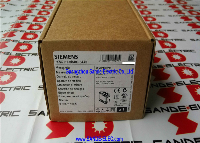
Siemens 7KM2112-0BA00-3AA0 | SENTRON PAC3200 Power Monitoring Device — LCD, 690/400V, 5A, 3-Phase, Modbus TCP, Class 0.5, 96×96mm Panel Mount, Wide-Range AC/DC Supply
Overview
The Siemens 7KM2112-0BA00-3AA0 is the SENTRON PAC3200 power monitoring device — a 96×96mm panel-mount energy meter and power quality instrument that measures and displays all primary electrical parameters of a three-phase network, communicates over Modbus TCP as standard, and stores energy totals for integration into building management and energy management systems.
At its core, the PAC3200 represents Siemens' answer to a persistent industrial requirement: a device compact enough to fit a standard DIN-sized panel cutout, readable directly from the front without a laptop, capable of communicating its data to a supervisory system, and accurate enough to satisfy metering accountability requirements.
The Modbus TCP interface — Ethernet-based, integrated as standard in the 7KM2112-0BA00-3AA0 — was the distinguishing feature that separated the PAC3200 from simpler panel meters when it was released.
Connecting a power monitor to an existing Ethernet infrastructure meant that the measured data could be read by SCADA systems, BMS (Building Management Systems), EMS (Energy Management Systems), or custom applications through the universally supported Modbus protocol without additional fieldbus hardware, gateways, or proprietary communication modules. The -3AA0 suffix specifically identifies this Ethernet/Modbus TCP variant.
Beyond Modbus TCP, the PAC3200 architecture supports optional expansion modules that add Modbus RTU (RS-485 serial), PROFIBUS DP, or PROFINET communication — making the same physical instrument adaptable to different communication infrastructure requirements.
A PROFIBUS module (7KM9300-0AB00-0AA0) or PROFINET module fits into the rear expansion slot without modifying the instrument itself, allowing the communication interface to be specified at installation rather than forcing a separate instrument purchase for each protocol.
The wide-range auxiliary power supply is a practical convenience that matters in international projects and mixed installations: the PAC3200 operates from 95–240V AC or 110–340V DC without any jumper setting or model variant change.
A single instrument type satisfies 120V North American, 230V European, and 110V DC panel supply requirements.
Key Specifications
| Parameter |
Value |
| Voltage Input |
L-L: up to 690V / L-N: up to 400V |
| Frequency |
45–65 Hz |
| Current Input |
5A (X/5A or X/1A CT) |
| Phases |
3-phase (or 1-/2-phase) |
| Communication (standard) |
Modbus TCP (Ethernet) |
| Communication (optional) |
Modbus RTU, PROFIBUS, PROFINET |
| Energy Accuracy |
Class 0.5 (IEC 61557-12) / Class 0.5S (IEC 62053-22) |
| Auxiliary Supply |
95–240V AC or 110–340V DC |
| Dimensions |
96 × 96 × 56mm |
| Panel Cutout |
92 × 92mm |
| Front Protection |
IP65 |
| Operating Temperature |
−10 to +55°C |
| Display |
Backlit LCD, 3 × 4-digit |
| Terminals |
Screw type |
What the PAC3200 Measures
The PAC3200 captures a comprehensive set of electrical parameters in real time. Voltage, current, and frequency are the basic measurements, from which the instrument computes:
Active power (P): The real power consumed that performs work — watts, kilowatts, megawatts. This is the primary billing parameter for most utility tariffs.
Reactive power (Q): The oscillating power exchange between source and inductive/capacitive loads — measured in kVAR. Relevant for power factor correction and demand tariff management.
Apparent power (S): The vector sum of active and reactive power — measured in kVA. Determines cable and transformer sizing requirements.
Power factor (cos φ): The ratio of active to apparent power. A low power factor indicates inefficient power use and may trigger utility surcharges.
The PAC3200 displays power factor for each phase and the three-phase sum.
Energy accumulation: The instrument maintains cumulative energy totals — kWh, kVARh, kVAh — with non-volatile memory that retains values through power interruptions. Both import and export totals are recorded, supporting bidirectional energy flow monitoring relevant in installations with on-site generation.
Harmonic content: The PAC3200 measures total harmonic distortion (THD) of voltage and current waveforms.
THD is an indicator of power quality and a diagnostic parameter for installations where variable-speed drives, switching power supplies, and other non-linear loads introduce harmonics into the network.
Min/max recording: The device records the minimum and maximum values of all measured parameters since the last reset, providing a historical record of operating extremes useful for troubleshooting events or verifying that design limits have not been exceeded.
Class 0.5 and Class 0.5S — Accuracy That Supports Accountability
The accuracy class designation on the PAC3200 — Class 0.5 per IEC 61557-12 and Class 0.5S per IEC 62053-22 — is not a marketing claim but a measurable performance standard that defines the instrument's maximum permissible energy measurement error across a specified range of operating conditions.
Class 0.5S (the "S" designation from IEC 62053-22) is a metering standard specifically defined for energy meters operating over a wide current range, from 1% to 120% of rated current, with specified limits on measurement error at all points in that range.
The Class 0.5S error limit is ±0.5% of reading at full rated conditions.
This accuracy level makes the PAC3200 suitable for sub-metering applications where energy allocation between tenants, cost centres, production lines, or buildings must be defensible — not just approximately correct but verifiably within a known error band.
For applications requiring utility-grade fiscal metering (tenant billing under tariff regulation), the governing authority's specific requirements must be verified against the PAC3200's certification, as fiscal metering requirements vary by jurisdiction and may impose additional approval conditions beyond the IEC standards.
Modbus TCP Integration
The PAC3200's Ethernet Modbus TCP interface uses the standard Modbus function code architecture over TCP/IP port 502. Every measured parameter, energy counter, and status flag in the instrument is accessible at a documented Modbus register address.
Standard Modbus client software — SCADA packages, building management systems, data historians, or custom-developed applications — can poll the PAC3200's register map without any proprietary software or communication driver beyond a standard Modbus TCP client library.
The instrument's register map documentation is published by Siemens and covers all parameters including voltage, current, power, energy counters, harmonic content, and min/max recorded values.
Multiple Modbus TCP clients can connect to the PAC3200 simultaneously — relevant in installations where a SCADA system and a local energy management dashboard both require access to the same measurement data.
The IP address is configured through the front panel interface, eliminating the need for a PC connection to set network parameters during installation.
DHCP is also supported for environments where addresses are assigned automatically.
FAQ
Q1: The PAC3200 is listed as discontinued. What is the recommended current-generation replacement?
Siemens has positioned the PAC3220 (front-mounted, with Ethernet/Modbus TCP as standard) and the PAC4200 series (for higher accuracy and expanded measurement functions) as successors.
For applications where the PAC3200's measurement capabilities and Modbus TCP interface are sufficient, the PAC3220 is the most direct replacement with a compatible physical format.
The PAC4200 adds additional energy quality functions and higher input voltage ratings.
Both successors maintain panel-mount form factors compatible with the PAC3200's 92×92mm cutout.
Q2: Current input is rated at 5A. Can the PAC3200 work with 1A secondary current transformers?
Yes — the PAC3200 accepts both X/5A and X/1A CT ratios.
The CT ratio is programmed into the device's configuration so that the displayed and communicated values reflect the actual primary current rather than the CT secondary current.
Selecting 1A secondary CTs reduces the burden on the CT secondary circuit and can improve accuracy when long cable runs between CT and meter introduce significant conductor resistance.
Both CT types use the same physical current input terminals on the instrument.
Q3: The instrument has IP65 protection at the front panel. Is the rear of the panel (wiring side) also protected?
No. IP65 applies only to the front face of the PAC3200 — the display bezel and pushbuttons — providing protection against dust and water jets from the front.
The rear terminals are rated IP20 (protection against solid objects greater than 12mm, no water protection).
The PAC3200 is designed for installation inside an electrical panel or enclosure, where the terminal side is protected by the enclosure's own ingress protection rating.
The instrument itself is not suitable for direct outdoor exposure or installation in an enclosure where water or contaminants can reach the rear terminal area.
Q4: The optional modules add PROFIBUS or PROFINET capability. Are these modules installed externally or inside the instrument?
The communication expansion modules (such as the PROFIBUS DP module 7KM9300-0AB00-0AA0) plug into a rear-mounted expansion slot on the PAC3200 body.
The module is physically integrated with the instrument — it does not require a separate enclosure or external mounting space.
The depth of the instrument increases when a module is installed (from 56mm to approximately 73mm with module), so panel depth must be verified before installation if clearance behind the panel is limited.
The module is accessible for replacement or upgrade without removing the front of the instrument from the panel.
Q5: Does the PAC3200 require an external current transformer, or can it directly measure phase current?
The PAC3200 does not include direct current measurement capability — it requires external current transformers (CTs) that reduce the measured phase current to a 5A (or 1A) secondary signal that the instrument reads. Direct connection to phase conductors for current measurement is not possible.
The CT secondary wiring connects to the IL1/k-l, IL2/k-l, and IL3/k-l terminals on the rear of the instrument.
For a new installation, the CT ratio selection depends on the maximum expected load current — the CT primary rating should be at or slightly above the maximum load current, and the ratio is then programmed into the PAC3200's configuration.


 Your message must be between 20-3,000 characters!