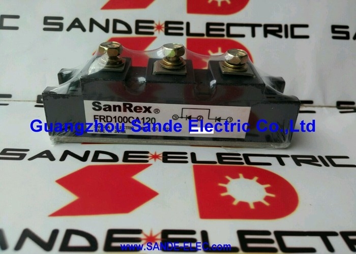
Sanrex FRD100CA120 | Fast Recovery Diode Power Module — 1200V / 100A / 1.80V Vfm / DCB / 2500V Isolation
Fast Recovery — Not the Same as Standard Rectifier Diodes
Standard diodes designed for 50/60 Hz mains rectification store junction charge when forward biased and release it as a reverse current pulse when the voltage reverses. At mains frequency this reverse recovery current is brief relative to the cycle time. In PWM inverter and high-frequency switching circuits where voltage reverses in microseconds, this reverse recovery current can be as large as the forward current and create destructive current spikes through adjacent switches.
Fast recovery diodes use optimised junction doping profiles, narrow base widths, and controlled minority carrier lifetimes to reduce stored charge and accelerate recovery. The FRD100CA120 stops conducting in the reverse direction in a fraction of a microsecond — a fundamental requirement for freewheeling diodes in IGBT inverter bridges, brake chopper circuits, and PFC boost stages.
DCB Substrate — Reliability Through Direct Bonding
DCB (Direct Copper Bonded) substrate bonds copper layers directly to a ceramic insulator through a high-temperature diffusion process — a metallurgical bond, not solder or adhesive. This provides lower thermal resistance from silicon junction to base plate and better resistance to thermal cycling fatigue than soldered ceramic structures. As the module heats and cools through years of service, the DCB substrate maintains its thermal connection where solder-bonded structures develop voids and delamination that progressively increase thermal resistance.
The DCB substrate also provides the 2500V isolation between the semiconductor devices (at DC bus potential) and the base plate (at heatsink ground), allowing direct mounting on a metallic heatsink without an additional isolating pad in most applications.
Key Specifications
| Parameter |
Value |
| Vrrm |
1200V |
| Ifa |
100A at Tc = 78°C |
| Vfm |
1.80V |
| Ifsm |
2000A |
| I²t |
16,600 A²s |
| Isolation |
2500V |
| Substrate |
DCB |
| Base Width |
34 mm |
Applications in Drive Power Electronics
| Circuit Position |
Why Fast Recovery Required |
| Inverter freewheeling diodes |
Reverse recovery current flows through the IGBT turn-on — slow recovery increases IGBT switching stress |
| PFC boost stage |
Diode switches at boost converter frequency (20–100 kHz) — slow recovery produces high switching losses |
| Brake chopper freewheeling |
Inductor current recirculates during chopper off-period at chopper switching frequency |
FAQ
Q1: What is the practical difference between fast recovery and ultrafast diodes?
Fast recovery diodes have reverse recovery times (trr) typically in the 100–500 ns range. Ultrafast diodes achieve trr below 100 ns. For industrial drive PWM at switching frequencies up to approximately 20 kHz, fast recovery is generally adequate. Above 50 kHz in high-performance converters, ultrafast or SiC Schottky diodes reduce switching losses further. The FRD designation indicates fast recovery — the exact trr is specified in the Sanrex datasheet.
Q2: Can the FRD100CA120 withstand a DC link short circuit without protection?
No. The Ifsm (2000A) is a single-event surge rating for a brief current pulse of defined duration. A sustained DC link fault delivers far higher energy. The I²t value (16,600 A²s) defines the total energy absorption limit. The upstream fuse must have an I²t let-through value lower than 16,600 A²s to protect the diode — the fault must clear before the energy through the module exceeds this limit.
Q3: How does the I²t value guide fuse selection?
For the diode to survive a fault, the upstream fuse's I²t let-through value must be less than the module's I²t rating of 16,600 A²s. Fuse manufacturers publish I²t let-through values in their selection tables as a function of fuse rating and prospective fault current. Select a fuse whose maximum let-through I²t at the installation's fault current level falls below 16,600 A²s.
Q4: What mounting procedure achieves the rated 100A capacity?
Apply thermal interface material (thermal grease or pre-cut thermal pad) between the module base plate and the heatsink. Tighten mounting screws to the torque specified in the Sanrex datasheet — uniform torque ensures adequate contact pressure without cracking the ceramic substrate. Size the heatsink for the module's conduction loss (approximately 180W at 100A with 1.80V forward voltage) plus adequate airflow to maintain Tc ≤ 78°C under continuous full-load operation.
Q5: Is the FRD100CA120 a direct substitute for equivalent modules from Semikron, Infineon, or Powerex?
The 34mm base package and 1200V/100A ratings are compatible with the international standard package used by those manufacturers. Mechanical fitment is generally interchangeable. Verify the dynamic parameters — trr, Qrr, Rth(j-c) — between the original module and the FRD100CA120 datasheet to confirm the substitution is appropriate for the specific circuit operating conditions.


 Your message must be between 20-3,000 characters!