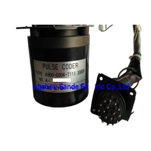
FANUC A860-0304-T113 Incremental Pulse Coder
3000 Pulses/Rev | Incremental Type | FANUC S-Series & Early Red Cap AC Servo Motors | Black Housing | Cable + Connector Included | Made in Japan
When the Encoder Fails, the Axis Stops
A CNC machine tool is only as accurate as the feedback it receives. The servo motor moves — but the control system only knows where the axis is because the encoder attached to the back of that motor is reporting position in real time. When the encoder develops a fault, whether through contamination, physical shock, age, or optical element degradation, the result is immediate: position alarms, erratic axis behavior, or a machine that simply refuses to run.
The FANUC A860-0304-T113 is the 3000-pulse-per-revolution incremental pulse coder for the early-generation FANUC AC servo motor family — the red cap S series motors that powered the axis drives on countless machining centers, turning centers, and milling machines throughout the 1980s and early 1990s. It mounts to the rear of the servo motor, reads the motor shaft's angular movement optically, and delivers the quadrature pulse stream that the servo amplifier and CNC control rely on to maintain position accuracy and speed regulation.
Technical Specifications
| Parameter |
Value |
| Part Number |
A860-0304-T113 |
| FANUC Description |
3000P INC ENCODER |
| Encoder Type |
Incremental (quadrature) |
| Resolution |
3,000 pulses per revolution |
| Output Signal |
A/B phase quadrature + Z (one-pulse-per-revolution) |
| Housing Color |
Black plastic |
| Mount Location |
Motor rear (shaft-end) |
| Cable |
Included with connector |
| Operating Temperature |
0°C to +40°C |
| Storage Temperature |
0°C to +50°C |
| Operating Humidity |
Max 80% RH (non-condensing) |
| Storage Humidity |
Max 80% RH |
| Country of Origin |
Japan |
| Cross-Reference |
A290-0561-V503 |
| Applicable Series |
FANUC A860-0304 |
3000 Pulses Per Revolution: Why This Number Exists
Within the A860-0304 encoder family, three variants exist: the T111 (2000P), the T112 (2500P), and this unit, the T113 (3000P). The pulse count is not an arbitrary spec — it maps directly to the last digit of the servo motor's part number.
FANUC's early AC servo motor naming convention encodes the encoder specification into the motor designation. A motor whose part number ends in a "B003" or "B203" suffix has a "3" as the final digit of that segment, which specifies a 3000-pulse encoder at the factory. A motor with B001 or B201 calls for a 2000P unit; B002 or B202 requires the 2500P. This systematic correlation means that when sourcing a replacement encoder, the motor part number itself is the primary reference. The A860-0304-T113 is correct for any motor where that last digit is 3.
Verified motor examples carrying the A860-0304-T113 include the A06B-0317-B003 (FANUC 10S/3000 AC servo motor) and A06B-0501-B203, among others in the 0, 0S, 0L, 5, 5S, 5L, 6L, 10, 10S, 20, and 20S series designation range.
The Red Cap Motor Family and Where This Encoder Lives
The FANUC AC servo motor family visible in older machine tools falls into two easily recognizable generations: the black cap motors (which are actually DC motors, identifiable by their yellow or black end caps) and the red cap motors, which are the brushless AC units that represent the early generation of the platform that dominates modern CNC. The A860-0304-T113 belongs firmly to the red cap era.
Physically, the encoder assembly mounts at the non-drive end of the motor — the rear face opposite the output shaft. The black plastic housing sits against the motor's rear bearing housing, secured by mounting screws, with the encoder's sensing element reading an internal code disk that rotates with the motor shaft. The cable and connector included with the assembly routes along the motor body toward the servo amplifier's feedback input.
Because the encoder is an incremental device, it tracks relative shaft movement from whatever reference position was last established. Unlike absolute encoders that retain position through power interruptions, the incremental A860-0304-T113 requires the CNC control to perform a reference return (homing cycle) on power-up before valid absolute position is established on the axis. This is normal behavior for the S-series drive system and is handled automatically by the CNC control through its reference return function.
Inside the Incremental Measurement Principle
The pulse coder works optically. An internal light source illuminates a spinning code disk that carries a pattern of evenly spaced transparent and opaque segments — 3000 segment pairs around the full 360-degree circumference. As the disk rotates with the motor shaft, two photodetectors displaced by a quarter-period generate the A and B phase output signals in 90-degree phase relationship (quadrature). A third track generates a single pulse per revolution — the Z pulse, or marker — which serves as the reference point for the homing sequence.
The quadrature relationship between A and B does two things: it doubles the effective resolution through edge-counting at the amplifier (each physical 3000-count cycle produces 12,000 countable edges in full quadrature counting mode), and it provides directional information — the sequence A-then-B versus B-then-A tells the servo amplifier which direction the shaft is rotating. Without this directional information, a speed controller cannot regulate closed-loop, and a position controller cannot track.
The servo amplifier's feedback circuitry monitors the pulse stream continuously. If the count deviates from the commanded trajectory, the amplifier corrects motor current to restore position. If the signal disappears entirely or shows pattern anomalies suggesting encoder malfunction, the amplifier generates a position feedback alarm that typically prevents further axis motion until the fault is diagnosed and cleared.
The A860-0304-T113 in the Maintenance Context
FANUC CNC maintenance technicians working on machines from the FANUC 0, 6, 10, 11, and 15 control generations will encounter this encoder regularly. The machines that used these controls — and the S-series motors they drove — were installed in enormous numbers globally during the machine tool boom years, and a substantial proportion of those machines remain in active production service today.
The most common failure presentation is a sudden position feedback alarm on the CNC, often accompanied by erratic axis behavior immediately before the alarm locks out the axis. Contamination reaching the encoder's optical path — coolant mist, metallic particles, or lubricant — is a frequent cause. Physical shock from a mechanical overrun can damage the code disk or the bearing within the encoder assembly. Connector and cable failures at the motor end also manifest as encoder faults, and should be checked before assuming the encoder itself has failed.
FANUC CNC specialists note that testing the A860-0304-T113 meaningfully requires running it installed on the actual motor, since bench-test arrangements that don't replicate the motor's shaft and mounting environment may not expose intermittent faults that only appear under rotational load and thermal conditions. This is why reputable FANUC maintenance suppliers test these encoders with the motor, not separately.
Cross-Reference: A290-0561-V503
The A860-0304-T113 carries an established cross-reference: A290-0561-V503. Both numbers refer to the same physical encoder unit. The A290-xxxx-Vxxx numbering format appears in FANUC parts documentation as an alternate designation for some early pulse coder assemblies, and it is the number that may appear in some machine tool builder's maintenance documentation or spare parts lists predating the standardization of the A860-xxxx-Txxx format. When searching aftermarket stock or cross-referencing a machine's spare parts documentation, both numbers should be checked against available inventory.
Frequently Asked Questions
Q1: How do I confirm that the A860-0304-T113 is the correct encoder for my specific FANUC servo motor?
The surest method is reading the motor's nameplate. FANUC's early AC servo motor part numbers follow a structured format where the last digit of the "B" designation segment encodes the encoder type: "1" = 2000P (T111), "2" = 2500P (T112), "3" = 3000P (T113). A motor with a part number ending in B003, B103, B203, or similar constructions where the final digit is 3 takes the A860-0304-T113. For motors from the 0, 0S, 5, 5S, 10, 10S, 20, and 20S size designations with that "3" suffix, this is the correct unit. If the motor's nameplate is damaged or illegible, FANUC specialists can cross-reference the motor's physical characteristics and amplifier type to confirm the correct encoder specification.
Q2: Can the A860-0304-T113 be substituted with the A860-0304-T111 (2000P) or T112 (2500P) if the T113 is unavailable?
Not directly. The servo amplifier's velocity and position loop calculations are calibrated to the specific pulse count of the encoder that was originally specified for the motor. Changing to a different pulse count requires corresponding parameter changes in the servo amplifier and CNC control — specifically the number of feedback pulses per motor revolution used in the velocity loop and CMR (command multiplication ratio) settings. Making those changes without thorough understanding of the drive system parameters risks miscalibrating the axis. In a maintenance context where a quick return to service is needed, sourcing the correct T113 is strongly preferred over attempting to adapt a different pulse count variant.
Q3: What CNC alarm codes typically indicate A860-0304-T113 encoder failure on FANUC 0, 6, 10, and 15 series controls?
The specific alarm numbers vary by CNC generation, but the category is consistently labeled as servo or position feedback alarms. On FANUC 0 series controls, alarms in the 400–499 range cover servo axis faults including feedback errors. The FANUC 6 and 10 series generate similar servo alarm categories. Common encoder-related presentations include "servo alarm: position feedback error," "disconnected pulse coder," or velocity loop instability alarms. The servo amplifier's LED indicators also provide diagnostic codes — most FANUC servo module families use an illuminated or blinking display that codes specific fault types, with feedback signal loss being one of the defined states. Always check the amplifier's diagnostic display alongside the CNC alarm readout.
Q4: Is this encoder available for purchase as a standalone part, or must it be replaced as part of a complete motor exchange?
The situation varies by supplier. Some FANUC specialists, particularly those focused on motor repair and refurbishment, only service the A860-0304-T113 as part of a motor repair transaction — because meaningful functional testing of the encoder requires the motor's shaft, bearings, and mechanical assembly. Others sell tested units on an outright or exchange basis, typically sourced from decommissioned motors or factory surplus. The quality of a standalone encoder purchase depends entirely on whether the supplier has conducted proper loaded testing on the assembly rather than a simple electrical continuity check. Given the age of this encoder generation, new-in-box stock is rare; refurbished or tested used units from reputable FANUC parts specialists are the realistic supply source in most markets.
Q5: What causes these encoders to fail, and what maintenance steps can extend their service life?
The optical elements are the primary wear points — the LED light source dims over time and operating hours, and the code disk's transparent segments can accumulate contamination that blocks or scatters light, degrading signal quality before complete failure occurs. Coolant mist penetrating the encoder housing is one of the most common environmental causes of failure in machine tool applications, particularly on horizontal machining centers where coolant management is more challenging. Preventing contamination ingress at the encoder connector and ensuring the motor's rear seal is intact where the encoder interfaces with the motor housing are the primary preventive measures. Periodic inspection of the encoder cable for chafing or connector corrosion, particularly on axes that undergo frequent travel and cable flexing, is also worthwhile. When a motor is disassembled for bearing replacement or rewinding, the encoder should be inspected and cleaned by a qualified technician before reinstallation.


 Your message must be between 20-3,000 characters!