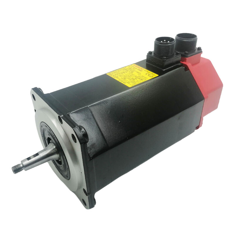
Home
>
Products
>
Industrial Servo Motor
>
The FANUC A06B-0151-B576 is an AC servo motor belonging to FANUC's Alpha (α) series — the workhorse generation of FANUC servo motors developed for large CNC machine tools, horizontal machining centres, boring machines, and heavy-duty rotary axis drives. Its internal designation within the series is α30/1200: a motor rated at 30 N·m stall torque and a maximum speed of 1,200 r/min.
Where most servo motors in smaller CNC machines operate at 3,000 r/min or more, the α30/1200 was engineered for a fundamentally different brief — sustained high torque at moderate speed, directly coupled to demanding feed axes without intermediate gearing. That combination of 30 N·m of stall torque and the physical scale the job demands means this is a substantial motor, weighing approximately 41 kg, and requiring crane or lifting equipment for safe handling.
Three defining features separate the B576 from other variants within the A06B-0151 family: the taper shaft, the αA64 absolute pulsecoder, and the S.C. (supercapacitor) backup system. Each of these is covered below.
| Parameter | Value |
|---|---|
| FANUC Model Designation | α30/1200 |
| Rated Output (continuous) | 3.3 kW |
| Peak Output | 4.8 kW |
| Stall / Rated Torque | 30 N·m |
| Maximum Speed | 1,200 r/min |
| Rated Voltage (from amplifier) | 191 V, 3-phase |
| Frequency | 80 Hz |
| Rated Current (continuous) | 11 A |
| Peak Current | 17 A |
| Back-EMF Constant | 83 V |
| Winding Resistance | 0.34 Ω |
| Shaft Type | Taper shaft (no brake) |
| Encoder | αA64 Absolute Pulsecoder + S.C. (supercapacitor) |
| Encoder Resolution | 64,000 pulses/revolution |
| IP Rating | IP65 |
| Ambient Operating Temperature | Up to 40°C |
| Motor Weight | Approx. 41 kg |
| Country of Origin | Japan |
The shaft configuration is one of the most practically significant features of this part number. A tapered shaft — rather than a straight keyed shaft — provides a mechanically superior coupling method when transmitting high torque levels. The tapered interface is drawn up by a drawbolt, creating a clamped metal-to-metal contact over the full taper length. This distributes clamping force across a wide area, eliminates the micro-movement and fretting that can occur at keyed-shaft connections under heavy cyclic loading, and effectively creates a zero-backlash, zero-slip coupling.
In the context of the α30/1200, where 30 N·m must be delivered with precision across thousands of CNC positioning cycles, this is not a minor engineering detail. Machine builders who specified taper-shaft motors for large-format horizontal machining centres and rotary tables chose this configuration because it holds alignment far more reliably over the long operational life of the machine.
When removing or replacing this motor, the taper fit must be released with a drawbolt extractor — never struck, hammered, or pried. Forcing the shaft off through mechanical shock risks permanent damage to both the motor shaft and the machine interface.
The encoder on the A06B-0151-B576 is the αA64 absolute pulsecoder, providing 64,000 pulses per shaft revolution. It is an absolute device: at any moment, it knows the exact angular position of the motor shaft without needing a reference return sequence.
The "+S.C." designation is the distinguishing encoder feature. S.C. stands for supercapacitor — an onboard energy storage component built into the pulsecoder unit that maintains the absolute position data during power interruptions, instead of relying exclusively on a separate battery. The supercapacitor charges during normal operation and provides enough stored energy to retain position data through planned shutdowns and brief power losses.
This is directly relevant to maintenance practice. When the encoder is disconnected from power for an extended period — for example, during a long storage interval or a motor swap — the supercapacitor will eventually discharge. If it discharges fully before the motor is recommissioned, the absolute position reference is lost and a single reference return (zero-point re-establishment) will be required at the CNC before normal operation resumes. In practical terms, a freshly connected A06B-0151-B576 that has been in storage should be powered up via its amplifier and left in an idle, energised state for a period to allow the supercapacitor to recharge before assuming absolute position data is valid.
The battery backup for absolute position data in the broader FANUC Alpha system is managed at the servo amplifier level, not inside the motor itself. This means removing the motor for service — without disturbing the amplifier or its battery — does not destroy the stored machine coordinate data at the CNC.
The α30/1200 motor series (A06B-0151-B***) is specified to pair with the SVM2-40/80 dual-axis servo amplifier module. Two amplifier generations covered this motor:
| Amplifier Module | Part Number | Interface |
|---|---|---|
| SVM2-40/80 (α Series) | A06B-6079-H207 | Standard Type A/B bus |
| SVM2-40/80 (αi Series) | A06B-6096-H207 | FSSB (Fibre-optic Servo Serial Bus) |
The A06B-6096-H207 (αi Series SVM) uses FANUC's FSSB optical fibre interface to communicate with the CNC. This interface — standard on FANUC Series 16i, 18i, 21i, and 0i control platforms — replaces the older parallel wiring architecture with a single high-speed fibre-optic cable running from the CNC to a chain of servo amplifier modules.
CNC controls compatible with the α30/1200 motor system include FANUC Series 0, 0C, 15A, 15B, 16A, 16B, 18A, 16i, 18i, 21i, and 0i — covering a wide span of production-era machining centres and lathes that commonly used this motor.
The α30/1200 was specified by machine builders for the heaviest feed axes in their CNC machine ranges. Typical applications include:
Large horizontal machining centres — B-axis (rotary pallet), W-axis (spindle quill), or Z-axis (column travel) on machines with tables in the 500 mm × 500 mm range and above, where the weight of the moving column or head demands sustained torque capability rather than high speed.
Horizontal boring mills — radial feed axes on boring tables, where precision positioning under load at low speed is the primary requirement.
Gear cutting and grinding machines — rotary axis drives requiring smooth, high-torque servo control over a limited angular range.
Heavy-duty CNC lathes — tailstock quill drives or live tooling axes on large-capacity turning centres.
The 1,200 r/min ceiling is not a limitation in these applications; it is a design feature. The motor's torque density — 30 N·m from a unit weighing 41 kg — reflects FANUC's winding and magnetic design optimised for sustained low-speed output rather than for the peak-speed performance demanded by high-speed machining axes.
Several shaft and encoder configurations exist within the A06B-0151 series. The B576 occupies the taper-shaft, absolute-encoder, no-brake position:
| Part Number | Shaft | Encoder | Brake |
|---|---|---|---|
| A06B-0151-B075 | Straight + keyway | αA64 | None |
| A06B-0151-B077 | Straight + keyway | αI64 (incremental) | None |
| A06B-0151-B177 | Taper | αI64 (incremental) | 35 N·m brake |
| A06B-0151-B576 | Taper | αA64 + S.C. (absolute) | None |
| A06B-0151-B577 | Taper | αI64 (incremental) | None |
The B576 is the combination of choice when the machine requires: a taper-shaft coupling for maximum torque transmission integrity, an absolute encoder to avoid reference-return cycles at startup, and no electromagnetic brake (vertical axes requiring a holding brake would typically select the B177 or an equivalent brake variant).
At approximately 41 kg, this motor should never be lifted or moved by hand alone. FANUC's own documentation is explicit on this point: use a crane, hoist, or appropriate lifting equipment. The eyebolt on the motor body is for single-motor lifting only — it must not be used to move the machine or any assembly beyond the motor itself.
Before commencing any electrical work, confirm that the servo amplifier and its associated power supply have been fully discharged. The DC bus capacitors in FANUC Alpha amplifier modules can retain dangerous voltages for several minutes after mains power is removed; the charge lamp on the amplifier module must be fully extinguished before any work on motor connections proceeds.
Do not perform a megger (insulation resistance) test on this motor with the encoder cable connected. The pulsecoder electronics are not rated for the 500 VDC test voltage used in standard insulation resistance testing. Disconnect the encoder before performing any such test on the motor windings.
Q1: What is the difference between the A06B-0151-B576 (αA64+S.C.) and the B577 (αI64) variant — and can they be exchanged?
The B576 carries an absolute pulsecoder (αA64) with supercapacitor backup. The B577 uses an incremental pulsecoder (αI64). These are not interchangeable without changes at the CNC and amplifier level. An absolute encoder motor allows the machine to resume normal operation after a power cycle without performing a reference return to re-establish axis position. An incremental encoder motor requires a reference return every time the machine is powered on, because the encoder only tracks position changes from the last known reference point — not absolute shaft position. If a machine was commissioned with a B576, substituting a B577 will disable the absolute feedback function and force a reference-return requirement at every startup. The replacement must match not just the mechanical configuration but the encoder type.
Q2: The motor has been in storage for several months. Will the absolute position data still be valid when it is installed?
Not necessarily. The supercapacitor inside the αA64 pulsecoder retains absolute position data during the motor's operational life, but after extended storage disconnected from power, the supercapacitor charge will gradually deplete. If the motor has been stored for more than a few weeks without connection to its amplifier, treat the absolute position data as potentially invalid. After installation and connection to the servo amplifier, allow the motor to remain powered in an idle state for a period to allow the supercapacitor to recharge via the amplifier's encoder supply. The CNC should then be taken through a reference return to re-establish the machine coordinate system before returning the axis to production use. Attempting to resume operation immediately with stale position data risks an axis positioning error.
Q3: The taper shaft is difficult to release — can it be struck or wedged off?
No. FANUC's documentation explicitly warns against using hammers or wedges on the taper shaft. The correct removal method is a drawbolt extractor — a threaded puller that engages the tapped hole in the shaft end and applies controlled axial force to break the taper engagement. Striking the shaft transmits shock loads directly into the encoder assembly and motor bearings, both of which can be damaged by impact that would seem mild by general mechanical standards. If the taper is very tight, apply penetrating fluid to the taper joint face, allow it to wick in, and then use the drawbolt extractor with steady, increasing force. Do not use heat; the encoder is thermally sensitive.
Q4: What servo amplifier is required, and can the motor run on a newer αi Series SVM if the original α Series amplifier is being replaced?
The α30/1200 is rated for the SVM2-40/80 dual-axis module. The original α Series version (A06B-6079-H207) uses a standard bus interface, while the αi Series equivalent (A06B-6096-H207) uses FANUC's FSSB fibre-optic interface. The A06B-0151-B576 motor is physically and electrically compatible with both amplifier generations — the motor windings, encoder type, and connector pinouts are unchanged. The critical factor is the CNC control: the αi Series SVM requires a FSSB-capable CNC (Series 16i, 18i, 0i, etc.), while the original α Series SVM is used with older Type-A or Type-B interface CNCs. Confirm the CNC generation before selecting the replacement amplifier module. Motor-to-amplifier parameter settings (motor type number, current limits) must also be verified in the CNC servo parameter table during commissioning.
Q5: This is a 3.3 kW motor — why does the rated voltage show 191 V rather than the 200–240 V supply voltage of the machine?
The 191 V is the output voltage from the servo amplifier to the motor, not the incoming mains supply voltage to the amplifier. FANUC Alpha Series servo amplifiers accept a standard 200–230 V AC three-phase mains input and convert it via the DC bus and PWM inverter stage into a variable-frequency, variable-voltage three-phase output to the motor. The 191 V / 80 Hz rating on the motor nameplate represents the amplifier output at rated operating conditions for the α30/1200, not the facility supply voltage. Applying 200 V AC mains directly to the motor terminals would destroy the windings — the motor must always be driven through a matched FANUC servo amplifier. This is standard practice for all FANUC Alpha Series servo motors without exception.
![]()
Contact Us at Any Time