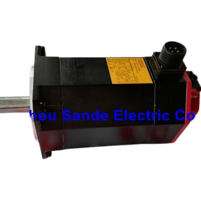
FANUC A06B-0078-B103 — AC Servo Motor βiS 12/3000, Straight Keyed Shaft, β128iA Encoder
What This Motor Is
The A06B-0078-B103 is a FANUC Beta iS series (βiS) AC servo motor, model designation βiS 12/3000 — the 1.8 kW member of a range that powers the feed and auxiliary axes of FANUC-controlled CNC machine tools worldwide. The "βiS" designation identifies it as part of FANUC's Beta intelligent Servo line: a family engineered specifically for economical CNC systems including FANUC Series 0i and 0i Mate controls, where the motor's cost and physical size must be kept compact without sacrificing the closed-loop accuracy that axis positioning demands.
This particular variant — the B103 — carries a straight shaft with slotted keyway and mounts the β128iA incremental Pulsecoder (FANUC part A860-2020-T301). No electromagnetic brake is fitted. That combination makes it the standard workhorse configuration for horizontal feed axes and other applications where the load does not need to be held mechanically at rest when the servo is de-energized.
Specifications at a Glance
| Parameter |
Value |
| Motor model |
βiS 12/3000 |
| FANUC part number |
A06B-0078-B103 |
| Rated output |
1.8 kW |
| Stalling torque |
11 N·m |
| Maximum speed |
3,000 r/min |
| Power supply (from amplifier) |
3-phase AC, 200 V class (138 V output from amplifier) |
| Shaft configuration |
Straight shaft, slotted keyway (SLK) |
| Brake |
None |
| Encoder type |
β128iA incremental Pulsecoder (A860-2020-T301) |
| Encoder resolution |
128,000 pulses/revolution |
| IP rating |
IP65 (connectors dripproof when mated) |
| FANUC manual reference |
B-65302EN (FANUC AC Servo Motor βiS Series Descriptions) |
The βiS 12/3000 in Context
FANUC structures its Beta iS series across a continuous torque-speed range — from the compact βiS 2/4000 at 0.5 kW up through the βiS 22/2000 at 2.5 kW. The βiS 12/3000 occupies a meaningful position in that range: at 1.8 kW and 11 N·m stall torque, it delivers enough torque for demanding feed axis work on mid-size machining centers and lathes while staying within the power class served by the βiSV 40 and βiSVSP amplifiers.
In practical terms, the "12/3000" model designation means the stall torque class is 12 N·m and maximum speed is 3,000 r/min. The torque-speed curve for this motor shows that the rated continuous output of 1.8 kW is maintained across the operating envelope, with intermittent overload capability — reaching considerably higher torque during acceleration bursts, consistent with FANUC's published overload duty profiles that allow 110% through 210% of rated torque for defined short-duration cycles. This reserve torque is what enables quick axis acceleration and deceleration on cycle-intensive machining operations.
Encoder: The β128iA Pulsecoder
The β128iA Pulsecoder fitted to the A06B-0078-B103 is FANUC's incremental position feedback device for the βiS series. It produces 128,000 pulses per revolution — a resolution that the FANUC CNC servo loop subdivides further through internal processing to achieve the sub-micron positioning repeatability expected of modern CNC axes.
Being an incremental encoder, the β128iA does not retain absolute position data across a power cycle. This is a key operational consideration: every time power is removed and restored, the CNC requires a reference return (zero return) operation before the axis can be used for precise positioning. For most machining center and lathe applications — where a reference return at startup is a standard part of the machine's power-on procedure — this is entirely normal. If the application demands absolute position retention across power cycles (eliminating the home return entirely), the motor would need to be replaced with an absolute-encoder variant from the same series, or the system architecture redesigned to incorporate an absolute encoder at the axis level.
Compatible FANUC Amplifiers and CNC Systems
The A06B-0078-B103 is designed to operate with FANUC's βi series servo amplifiers, connected to the CNC via FSSB (FANUC Serial Servo Bus) optical interface. Confirmed compatible amplifier types for the βiS 12/3000 motor include:
Single-axis amplifiers:
- βiSV 40 — the primary single-axis digital servo amplifier for this motor class
Combined servo/spindle amplifiers:
- βiSVSP 40/40-15 — used in economical lathe configurations pairing servo and spindle control in a single unit
- βiSVSP 40/40-18 — higher-capacity version of the combined unit
CNC systems:
- FANUC Series 0i-MODEL D
- FANUC 0i Mate-MODEL D
- Broader αi/βi series amplifier compatibility via FSSB connection
Motor type parameter numbers for the βiS 12/3000 under HRV2 control with a 20A amplifier are documented in FANUC manual B-65302EN — these must be set correctly when commissioning a replacement motor or when the drive parameters need to be re-established after amplifier replacement.
Physical Construction and Environmental Ratings
The motor body is constructed to the IP65 standard: fully sealed against dust and protected against water jets from any direction, when the power and encoder connectors are properly mated with their cable connectors. When connectors are unmated — for example during storage or transportation — the motor-side connectors should be capped to maintain the seal. FANUC specifies that for the βiS series from β4iS upward, the signal and power connectors are dripproof when engaged.
Storage temperature range per FANUC's βiS series specifications is −20°C to +60°C, with the motor to be kept away from condensation-prone environments, extreme temperature cycling, and locations with high vibration or significant dust. This is relevant when holding stock for maintenance purposes — proper indoor dry storage preserves encoder optics and bearing grease for extended periods.
The straight keyed shaft (SLK configuration) on the B103 is designed for reliable torque transmission through a standard keyed coupling or pulley. FANUC's installation guidance requires that the key be fitted whenever the motor is running; running a keyed shaft without the key can cause shaft imbalance or impair torque transfer at the connection point.
A06B-0078 Series — Variant Reference
All variants in the A06B-0078 family share the βiS 12/3000 motor core — the same stator, rotor, and torque characteristics. What differs is the shaft type, brake presence, and (in some suffix-coded variants) oil seal specification:
| Part Number |
Shaft |
Brake |
Encoder |
| A06B-0078-B003 |
Tapered |
None |
β128iA |
| A06B-0078-B103 |
Straight, keyed |
None |
β128iA |
| A06B-0078-B203 |
Straight, keyed |
None (oil seal variant) |
β128iA |
| A06B-0078-B303 |
Tapered |
24 V DC brake |
β128iA |
Selecting the wrong variant for a replacement — particularly mistaking a brake motor for a non-brake motor — creates a safety risk on vertical axes and an electrical integration mismatch, since the brake coil requires a separate 24 VDC supply. Always verify the installed motor's nameplate against the B-suffix code before ordering.
FAQ
Q1: What is the difference between the A06B-0078-B103 and the A06B-0078-B003?
Both are βiS 12/3000 motors with 1.8 kW rated output, 11 N·m stall torque, no brake, and the β128iA incremental encoder — electrically identical. The sole difference is the shaft. The B003 has a tapered shaft, which is standard on FANUC spindle-related or decelerator-coupled applications where the tapered fit provides a mechanically robust, zero-backlash connection to a mating hub. The B103 has a straight keyed shaft, the more common configuration for feed axes with straight-bore couplings, timing belt pulleys, or gearboxes using standard keyway connections. Verify the machine's mechanical interface — taper bore vs. straight bore — before ordering a replacement.
Q2: Which FANUC CNC controls and servo amplifiers are compatible with this motor?
The A06B-0078-B103 connects to FANUC βi series servo amplifiers via the FSSB optical interface. The primary compatible amplifier is the βiSV 40 for standalone single-axis installations. In combined servo/spindle configurations common on entry-level and mid-range lathes, the βiSVSP 40/40 series amplifiers (15 A and 18 A variants) also drive this motor. On the CNC side, the motor is qualified for use with FANUC Series 0i-MODEL D, 0i Mate-MODEL D, and related 0i-family controls. For earlier Series 0i-C systems, compatibility should be confirmed against the machine builder's documentation and FANUC's motor type parameter tables in manual B-65302EN.
Q3: Why does the machine need a reference return after power-on with this motor?
The β128iA Pulsecoder on the A06B-0078-B103 is an incremental encoder. It generates position counts only while running — it has no memory of shaft position between power cycles. When the CNC is powered down, position information is lost. At the next startup, the CNC has no knowledge of where the axis physically is until it performs a reference return (sometimes called G28 or zero-return), which drives the axis to its home position switch and re-establishes the known coordinate reference. This is normal operating procedure for machines using incremental feedback. If your application cannot tolerate a home-return sequence at each startup — for example, on a pallet-changing cell where re-homing causes production interruption — then an absolute-encoder motor variant would be the appropriate solution instead.
Q4: Can this motor be used as a drop-in replacement for an αiS series motor on the same machine?
Generally, no — not without careful system-level review. The βiS and αiS series are both FANUC servo motor families, but they differ in encoder interface, amplifier family, and CNC parameter sets. The βiS series was designed for the βi amplifier family and lower-cost CNC systems (0i), while the αiS series is matched to the αi amplifier family and higher-performance controls. Mixing them requires verifying that the amplifier in the machine is compatible with the replacement motor's encoder protocol, that the physical dimensions and shaft configuration match, and that the motor type parameter in the CNC is updated correctly. Replacing a failed βiS motor with another βiS motor of the same model is always the safest and fastest path to restoring machine function.
Q5: What are the most common failure modes for the A06B-0078-B103, and what should be inspected before installation?
The three failure points that account for most service events on FANUC βiS series motors are the encoder (Pulsecoder), bearings, and seals. Encoder failures typically manifest as CNC alarm codes related to pulse count errors or feedback signal loss — the β128iA is sensitive to shock, contamination of the optical sensor window, and voltage supply irregularities on the 6V encoder power line. Bearing failures are usually detectable by abnormal noise during rotation or vibration feedback in the CNC's servo diagnostic data before complete failure occurs. Seal degradation — particularly around the shaft-through opening — can allow coolant or cutting fluid to migrate into the winding and encoder area over time.
Before installing a replacement A06B-0078-B103, inspect the motor-side encoder connector and power connector for corrosion or mechanical damage, verify the shaft keyway is undamaged and the key is present, and check that the cable-side mating connectors are clean and fully seated before power-on. Do not perform insulation resistance tests (megger tests) on the motor with the encoder connected — the Pulsecoder electronics will be damaged by the test voltage.

 Your message must be between 20-3,000 characters!