Fanuc A06B-0116-B403 | Beta iS Series AC Servo Motor BiS1/6000 — 0.5kW, 1.2Nm, 6000RPM, 24V Brake, b64ia Encoder, Standard Connector
Overview
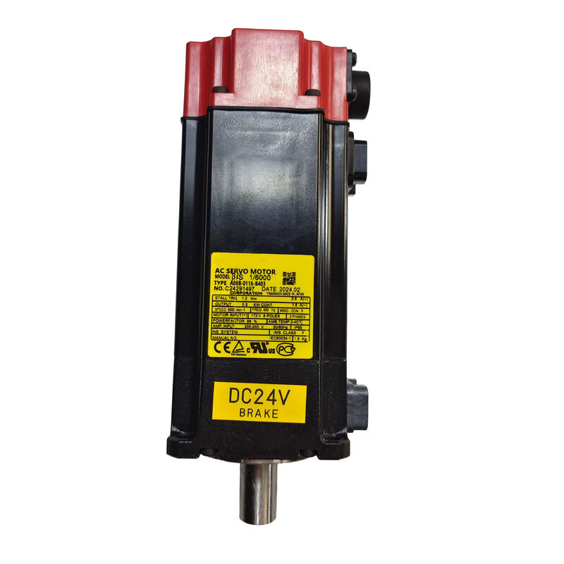
The Fanuc A06B-0116-B403 is a Beta iS series AC servo motor — model BiS 1/6000 — combining 0.5 kW output, 6,000 RPM maximum speed, a 24V DC spring-applied brake, and the b64ia battery-free absolute pulsecoder in a compact, single-axis package with a standard encoder connector.
It is the brake-equipped member of the BiS 1/6000 family, specified for axes where mechanical holding is a safety or quality requirement, while sharing the identical electromagnetic design, speed capability, and encoder specification of the brake-free B103 variant.
This is a motor that earns its specification when the application demands it.
On any axis where servo power removal could allow unwanted movement — a vertical axis that would drop its load, an inclined conveyor that would drift backward, a rotary axis that must hold its indexed position between operations — the 24V spring-applied brake delivers the fail-safe mechanical holding that servo torque alone cannot provide during power interruptions, E-stops, or programmed pauses.
The motor produces no torque when de-energised; the brake holds position in its place.
The standard connector configuration distinguishes this variant from the #0100 sealed version.
Where the #0100 adds enhanced sealing at the encoder cable connector junction for environments with direct fluid exposure, the standard A06B-0116-B403 uses the conventional connector engagement that is appropriate for the majority of CNC machine tool and automation installations — protected within enclosures or positioned away from direct coolant spray.
Most installations do not require the sealed connector's additional protection level, and the standard version is the more common specification in factory-floor machine tool applications.
Key Specifications
| Parameter |
Value |
| Rated Output |
0.5 kW |
| Stall Torque |
1.2 Nm |
| Maximum Speed |
6,000 RPM |
| Motor Voltage |
172 VAC |
| Rated Current |
1.8 A |
| Maximum Current |
2.6 A |
| Shaft Type |
Straight Plain (SLK — No Keyway) |
| Shaft Diameter |
14 mm |
| Brake |
24V DC Spring-Applied |
| Encoder |
b64ia Absolute Pulsecoder |
| Connector |
Standard (Non-Sealed) |
| Weight |
Approx. 2 kg |
| Series |
Fanuc Beta iS — BiS 1/6000 |
| Compatible Amplifier |
Beta i Servo Amplifier |
BiS 1/6000 in Practice — What 0.5kW at 6,000 RPM Means
The BiS 1/6000 is not a motor you would specify for a machine's primary cutting axis on a machining centre.
It is the motor you specify for the axes that keep a machine productive without demanding the same physical scale as the main axes: a tool change arm that must index precisely to each position, a pallet clamp mechanism that must hold a defined torque, a fourth-axis rotary table on a compact VMC where the load is light and the primary requirement is accurate positioning.
At 0.5 kW, 1.2 Nm stall torque, and 6,000 RPM, the BiS 1/6000 covers this auxiliary axis territory effectively.
The 6,000 RPM ceiling means the motor can complete rapid positioning moves quickly even when the mechanism's transmission ratio keeps the load speed low — the motor's headroom above typical operating speeds shortens the positioning time by allowing the acceleration and deceleration phases to operate well within the motor's torque capability.
The 1.2 Nm stall torque, while modest by primary axis standards, is fully adequate for the light mechanisms and low friction loads these axes typically present.
The 24V DC brake adds the holding capability that turns a positioning motor into a clamping mechanism.
On a rotary indexer, the motor positions to the commanded angle, the brake engages before the servo disables, and the indexed position is mechanically locked regardless of what happens to the control system or power supply afterwards.
The load cannot drift. The part does not move. Production quality is maintained through the entire machining cycle.
24V DC Brake Operation — The Engineering Logic of Spring-Applied Design
The phrase "spring-applied brake" describes a brake that is engaged by mechanical force rather than electrical force. In the A06B-0116-B403, a set of pre-compressed springs holds the brake disc against the motor shaft at all times.
Applying 24V DC to the brake coil creates an electromagnetic field that compresses the springs and lifts the disc away from the shaft, allowing it to rotate freely. Remove the 24V — for any reason — and the springs push the disc back against the shaft immediately.
The engineering logic is straightforward: a system that requires active electrical power to remain in the safe state is inherently more dangerous than one that defaults to the safe state without power.
A spring-applied brake defaults to engaged, which means the safe state (shaft locked) is the default state.
The unsafe state (shaft free to rotate) requires sustained 24V DC to maintain. Power failure, E-stop, servo alarm, control restart, intentional servo disable — all result in the brake engaging automatically, without any control system intervention.
For the auxiliary axes and peripheral mechanisms where the BiS 1/6000 is commonly used, this fail-safe behaviour directly protects against the consequences of unplanned events. A tool change arm that drops between positions during a power interruption can damage the tool and the spindle.
A pallet clamp that releases during a control restart allows the pallet to move. A rotary indexer that drifts during an E-stop may cause a collision on machine restart. The 24V brake on the A06B-0116-B403 prevents all of these outcomes by ensuring that the axis is mechanically locked the moment servo power is removed.
b64ia Absolute Pulsecoder — Battery-Free Position Retention
The b64ia pulsecoder built into the A06B-0116-B403 provides absolute shaft position data without a battery. At every power-up, the encoder communicates the exact angular position to the Beta i servo amplifier before any axis movement occurs.
The drive and CNC have correct position data from the first scan cycle, without any homing traversal.
For a brake-equipped axis, this matters in two ways.
First, it confirms that the brake engaged at the correct position during the previous power-down: if the CNC reads a position at power-up that is different from the commanded position at power-down, the discrepancy is immediately detectable and actionable before any motion commands are sent.
Second, it eliminates the homing sequence that incremental encoder axes require — particularly valuable on axes whose homing move would be complicated by the brake (the sequence of: enable servo, release brake, traverse to reference, re-engage brake, disable servo adds time and requires careful sequence design to execute safely).
Battery-free absolute position is the practical advantage that distinguishes the b64ia from encoder systems that require a battery to retain absolute position data.
There is no battery to source, fit, monitor, or replace. There is no risk of position loss on battery discharge. The encoder system works the same way on the machine's first power-up of the week as it does five years later.
SLK Shaft — Plain Straight, No Keyway
The SLK designation identifies the plain straight shaft without a keyway — the standard shaft configuration for this motor class in most Beta iS applications. The 14mm diameter shaft transmits torque through friction with the coupling hub bore, relying on the clamping force generated by the hub's locking mechanism.
Note for reference: the original product description from some suppliers incorrectly describes the SLK shaft as "tapered." The shaft on the A06B-0116-B403 is a plain straight cylindrical shaft, not tapered.
A Fanuc tapered shaft would be identified by the "TPR" suffix code, which this motor does not carry.
At 1.2 Nm stall torque and the corresponding peak current transients, the coupling clamping force must be specified for the motor's peak output rather than the rated stall torque alone. Hub bores machined to the correct tolerance for a 14mm shaft, with clamping mechanisms torqued to the coupling manufacturer's specification, handle these loads reliably. Periodic re-check of clamping torque — particularly after the first 50–100 hours of operation when initial seating occurs — is the primary mechanical maintenance task for plain shaft coupling interfaces.
B403 vs B103 — The Brake Dimension
The A06B-0116-B403 and A06B-0116-B103 are identical in every electrical and mechanical specification: same 0.5 kW output, same 1.2 Nm stall torque, same 6,000 RPM maximum speed, same 172V motor voltage, same 1.8A rated / 2.6A peak current, same 14mm shaft, same b64ia encoder, same amplifier compatibility. The number that changes — B4xx versus B1xx — marks the presence or absence of the brake.
This means the decision between them is purely an application question: does the axis need mechanical holding when the servo is off?
The answer depends on gravity and residual loads.
A horizontal axis with a light load and no gravity component has no tendency to move when the servo is off — the B103 without brake is the correct and simpler specification.
A vertical axis that carries load downward, an inclined axis, or any axis where the mechanism's friction is insufficient to hold position against the load force — these require the B403's brake.
Installing a B103 (no brake) on an axis that should have a brake creates a risk that only manifests when power is removed: the axis will drift, and the direction and distance of drift is not controlled.
Installing a B403 (brake) on an axis that doesn't need a brake wastes the brake's cost and adds the 24V brake supply circuit to the installation, but creates no safety risk. When there is genuine uncertainty about whether the load requires holding, the B403 is the conservative specification.
FAQ
Q1: What is the difference between A06B-0116-B403 and A06B-0116-B403#0100?
Both are BiS 1/6000 motors with a 24V DC brake, b64ia encoder, and plain straight shaft — identical in performance and electrical specifications.
The #0100 suffix on the second variant adds enhanced sealing at the encoder cable connector junction, making it appropriate for environments with direct coolant or fluid exposure at the connector area.
The standard A06B-0116-B403 uses the conventional connector engagement that suits the majority of machine tool installations where the motor is positioned away from direct fluid contact.
If the original failed motor is the #0100 variant, a standard A06B-0116-B403 can replace it mechanically and electrically but the encoder cable connector may not mate correctly without the sealed connector housing.
Q2: How does the 24V brake integrate with the Fanuc Beta i amplifier?
The Beta i servo amplifier controls the brake release as part of the servo enable/disable sequence. When the servo is enabled and ready, the amplifier signals the machine's 24V DC brake power supply to release the brake — 24V is applied to the brake coil, the spring force is overcome, and the shaft rotates freely under servo control.
When the servo is disabled — at E-stop, programmed axis stop, or servo alarm — the amplifier removes the brake release signal before the servo output is turned off, so the brake engages while the motor still has active position control. This sequencing prevents the load from moving during the handover from servo torque to brake holding.
Q3: Can the A06B-0116-B403 replace a B103 (no brake) on the same axis?
Yes, physically and electrically the motors are interchangeable at the motor itself. The installation additionally requires a 24V DC brake supply circuit and wiring to the motor's brake connector pins — which do not exist in a B103 installation.
If the axis was originally wired for a B103, adding the B403 requires adding the 24V brake supply connection, configuring the amplifier's brake interlock parameter, and verifying the brake release and engagement sequence operates correctly before returning the axis to production.
The reverse — replacing a B403 with a B103 on an axis that required braking — requires an engineering review to confirm the axis is safe without mechanical holding.
Q4: What happens to the brake if 24V DC is accidentally applied continuously without the amplifier controlling the release sequence?
If 24V DC is applied permanently to the brake coil without the amplifier's sequencing control, the brake remains released continuously — the spring-applied engagement mechanism is held open as long as the voltage is present.
The shaft rotates freely and no holding is provided when the servo is off. This is a wiring or control configuration error, not a brake failure, but it eliminates the safety function of the brake entirely.
The correct configuration requires the 24V supply to be switched by the amplifier's brake interlock output or by a relay under the servo enable/disable logic, not wired to a permanent 24V supply.
Q5: What are the pre-installation checks for a used A06B-0116-B403?
Test the brake before mechanical installation: apply 24V DC across the brake terminals and verify the shaft rotates freely with no drag; remove 24V and confirm the shaft is firmly held. Any drag under 24V indicates residual disc contact from a worn or contaminated brake disc.
Any shaft movement under spring engagement alone indicates the spring force is insufficient — the brake requires service before installation.
Additionally, rotate the shaft by hand to check bearing smoothness, inspect the encoder connector and cable exit for damage, and measure phase-to-phase winding resistance for balance.
A run-up on a compatible Beta i amplifier to 6,000 RPM with brake function verified at intermediate speeds confirms the motor is production-ready before it goes into the machine.


 Your message must be between 20-3,000 characters!