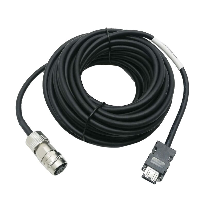
Mitsubishi MR-JHSCBL2M-H | Servo Encoder Feedback Cable — 2m, High Bending Life, HC-SFS / HC-LFS / HC-UFS / HC-RFS Series, MR-J2S Amplifier
Overview
The Mitsubishi MR-JHSCBL2M-H is a 2-metre encoder feedback cable for Mitsubishi's MELSERVO MR-J2S series servo system.
It carries the position and speed feedback data from the motor's encoder back to the MR-J2S servo amplifier — the closed-loop signal that determines where the motor shaft is at every moment of operation.
Without this cable working correctly, the servo loop is open, the amplifier cannot control position or speed, and the machine axis cannot function.
The cable arrives with factory-terminated connectors at both ends: the amplifier-side connector mates directly with the CN2 encoder input socket on the MR-J2S amplifier, and the motor-side connector mates with the encoder connector on the compatible HC-series motor. There is no field wiring, no crimping, and no pin insertion required — the installation is a plug-in procedure.
This factory termination is not merely convenient. The encoder feedback signal operates at low voltage and low current levels, and any poorly-terminated connection introduces contact resistance variation, intermittent signal loss, or ground noise that the servo amplifier reads as encoder faults. Mitsubishi's factory-crimped and tested connector assemblies eliminate this risk at the most signal-critical points in the cable's path.
The -H suffix in the part number carries a specific technical meaning established by Mitsubishi in their servo cable specifications: it identifies a long bending life construction, as distinct from the -L suffix standard bending life cable.
The MR-JHSCBL2M-H is built for installations where the cable undergoes repeated flexing — cable carriers (energy chains), moving saddles, robot arms, and similar dynamic applications where the cable travels through a bend repeatedly throughout the machine's operating life.
A standard -L cable used in a dynamic application will develop internal conductor fatigue fractures at the flex point over time, producing the kind of intermittent encoder fault that is difficult to diagnose because the cable appears intact externally.
The -H cable's stranding construction, insulation material, and jacket compound are all specified to resist this fatigue mechanism for a substantially longer service life under continuous flexing.
The cable is compatible with the HC-SFS, HC-LFS, HC-UFS, and HC-RFS motor series — the medium-to-large frame motors in Mitsubishi's MELSERVO motor lineup — as well as the 2000r/min HA-LFS series.
These motors use the same encoder connector pinout, allowing the MR-JHSCBL2M-H to serve across the compatible motor range without variant selection by motor frame size.
A separate cable family (the MR-JCCBL series) serves the smaller HC-KFS and HC-MFS motors, which use a different motor-end connector format.
Key Specifications
| Parameter |
Value |
| Cable Length |
2m |
| Bending Life |
-H (Long bending life / high flex) |
| Amplifier Connection |
MR-J2S amplifier CN2 encoder input |
| Motor Connection |
HC-SFS / HC-LFS / HC-UFS / HC-RFS / HA-LFS encoder connector |
| Compatible Amplifier |
MR-J2S series (up to 700A/CP/CL) |
| Compatible Motors |
HC-SFS, HC-LFS, HC-UFS, HC-RFS, 2000r/min HA-LFS |
| Termination |
Factory-assembled connectors both ends |
| Oil Resistance |
No — not oil-resistant |
| Origin |
Japan |
| Standard |
MELSERVO MR-J2S series accessory |
Long Bending Life (-H) — The Construction Difference
The distinction between -H and -L bending life is a material engineering difference, not a marketing classification. Mitsubishi achieves the long bending life rating through several design choices applied simultaneously throughout the cable cross-section.
The conductor stranding uses finer wire strands than standard flex cables — more strands of smaller diameter wire, which distributes the mechanical stress of bending across a larger number of conductor elements.
When a cable is bent repeatedly, the strain at the outer radius of the bend is taken by the conductor strands in tension. With finer stranding, each individual strand sees a smaller strain increment per bend cycle, and the cumulative metal fatigue damage per unit of bending cycles is lower.
The insulation material on the individual conductors is formulated for flexibility at a wider temperature range, avoiding the embrittlement that standard PVC insulation develops after sustained exposure to industrial temperature cycling.
The outer jacket compound is similarly selected for wear resistance and repeated flexing without cracking.
Together, these material choices extend the cable's service life in a cable carrier or on a moving axis from a fraction of what a standard cable provides to a figure that matches or exceeds the expected maintenance interval of the machine itself.
For a fixed installation — where the cable is routed in conduit, clamped, and never flexed after initial setup — the -H cable still functions correctly, but the bending life advantage is not exercised.
In that context, the -L standard cable would also suffice. The -H is the correct choice whenever the cable path involves a cable carrier, a revolving door entry, a moving bridge, or any routing where the cable bends and unbends cyclically.
Encoder Signal Integrity and Cable Routing
The encoder feedback data from the HC-series motor uses a serial communication protocol over the cable's internal conductors.
This is not a simple pulse count — the encoder generates a serial data packet containing position, speed, and encoder health information that the MR-J2S amplifier processes each servo cycle (at 125µs intervals in standard MR-J2S operation).
Any degradation in signal quality — increased noise, marginal voltage levels, intermittent contact — translates directly into servo alarm conditions on the amplifier.
For this reason, encoder cable routing warrants the same care as routing the cable itself.
Keep the encoder cable physically separated from power cables (motor U/V/W phases and main circuit power) wherever possible; electromagnetic induction from switching current in motor power cables couples noise into the encoder signal if the two cable types are bundled together in the same conduit.
Where separation is not possible, cross the two cable types at right angles rather than running them in parallel.
The encoder cable's shield must be connected at the amplifier end according to Mitsubishi's wiring diagram — grounding the shield at both ends on this type of cable creates a ground loop that can introduce low-frequency hum into the signal rather than rejecting it.
Compatible Motor and Amplifier Reference
The MR-JHSCBL2M-H is the 2m length in a family of same-specification cables that differ only in length. The same -H long bending life construction and motor/amplifier compatibility apply across the range: MR-JHSCBL5M-H (5m), MR-JHSCBL10M-H (10m), MR-JHSCBL15M-H (15m), and MR-JHSCBL20M-H (20m).
When an application requires a cable run longer than the standard lengths available, the MR-J2S system also supports a junction connector approach with intermediate cable sections — consult the applicable MR-J2S servo amplifier instruction manual for the maximum total encoder cable length and the recommended approach for longer runs.
The 2m length of the MR-JHSCBL2M-H places it in a specific installation context: it is primarily used where the servo amplifier and motor are in close proximity — a drive cabinet mounted directly beside or on the machine, or a machine design where the motor-to-cabinet distance is deliberately kept short to allow a 2m cable run with some slack for movement and maintenance.
For larger machines where the cable carrier run from the cabinet to the motor axis is longer, the 5m or 10m variants are more common.
Handling and Storage
The MR-JHSCBL2M-H is not rated for resistance to cutting oils, hydraulic fluids, or water-soluble coolants.
In machine tool installations where coolant mist or fluid splashing is present near the motor, the cable must be physically protected — either routed through sealed conduit, protected with a split sleeve or corrugated conduit jacket, or kept within the machine's guarded cable carrier system.
Coolant ingress into the cable jacket eventually degrades the insulation and can cause intermittent encoder faults that are diagnosed as encoder failures rather than cable installation problems.
For storage, keep the cable in its original packaging in a dry environment away from direct sunlight and UV exposure.
Do not coil the cable around a radius tighter than the minimum bend radius specified for the cable — sustained sharp bending during storage pre-stresses the conductors and reduces the service life from the first installation.
FAQ
Q1: What is the functional difference between the MR-JHSCBL2M-H (-H) and MR-JHSCBL2M-L (-L) cables for the same installation?
Both cables carry the same encoder feedback signals with identical connector terminations and motor/amplifier compatibility.
The difference is entirely in conductor construction and jacket material — the -H is built for repeated flexing in dynamic applications (cable carriers, moving axes), while the -L is adequate for static or semi-static installations where the cable is routed and clamped in position. In a fixed installation that is never disturbed, both cables will provide the same electrical performance.
In a cable carrier application that flexes thousands of times per shift, the -H will outlast the -L by a substantial margin before conductor fatigue fractures create intermittent faults.
Q2: The MR-JHSCBL series and the MR-JCCBL series both say "encoder cable for MR-J2S" — what is the difference and which one does my motor need?
The two series serve different motor families within the MR-J2S system.
The MR-JHSCBL series (including the MR-JHSCBL2M-H) serves the HC-SFS, HC-LFS, HC-UFS, and HC-RFS medium-to-large frame motors, which use a specific encoder connector format at the motor end.
The MR-JCCBL series serves the smaller HC-KFS and HC-MFS motors, which use a different motor-side connector with a junction connector intermediate.
Identify your motor from its nameplate label (HC-SFS, HC-LFS, HC-UFS, HC-RFS = JHSCBL; HC-KFS, HC-MFS = JCCBL). Using the wrong series cable will not physically connect — the connector formats are different — so a misidentification is immediately obvious at installation.
Q3: Can this cable be extended with a splice or junction connector if 2m is insufficient?
Splicing is not recommended. Any splice in an encoder cable introduces a point of resistance variation, potential for oxidation over time, and a mechanical weak point.
The MR-J2S encoder feedback operates on a serial data protocol with strict timing requirements; even marginal signal degradation at a junction can cause intermittent data errors that the amplifier interprets as encoder faults.
The correct approach is to order the next available standard length (5m, 10m) that provides adequate cable run with appropriate routing slack. If the Mitsubishi standard lengths do not suit the specific cable run geometry, junction connector assemblies using Mitsubishi's specified intermediate components are documented in the MR-J2S instruction manual as the supported long-run solution.
Q4: What servo alarm code appears when the MR-JHSCBL2M-H has failed or developed a fault, and how is it diagnosed?
On the MR-J2S amplifier, encoder communication faults typically manifest as Alarm 16 (Encoder communication error) or related encoder alarms in the A1x-A3x range depending on the specific fault type.
These alarms can arise from the cable itself (conductor fatigue fracture, shield damage), the connectors (contaminated or poorly-seated), or the motor encoder (failed sensing element).
To isolate the cable: inspect the full cable length for kinking, crush damage, or sharp bends at the cable carrier entry; unplug and reseat both connectors; and if available, substitute a known-good cable from another axis. If the alarm clears with the substitute cable and returns with the original, the cable is the fault source.
Q5: How should the cable be routed in a cable carrier to maximise its service life?
Follow these principles: the cable carrier's minimum bend radius must not be less than the cable's specified minimum dynamic bend radius — forcing a cable through a tighter bend than its specification accelerates fatigue.
Leave approximately 10–15% excess cable length within the carrier beyond the geometric length needed for the travel — this slack allows the cable to move freely within the carrier without tension at either end of travel.
The cable should not be twisted — it must lie flat in the carrier's travel plane. Bundle the encoder cable only with other signal cables in the carrier, not with motor power cables, to maintain noise isolation. Periodically inspect the cable at the cable carrier entry and exit points (where bending stress concentrates) for early signs of jacket wear or deformation.


 Your message must be between 20-3,000 characters!