Sanyo Denki 103H7126-0740 | SANMOTION F2 2-Phase Hybrid Stepping Motor — 1.27Nm, 1.8°, 56mm Frame, 3A Unipolar, 24V, Lead Wire
Overview
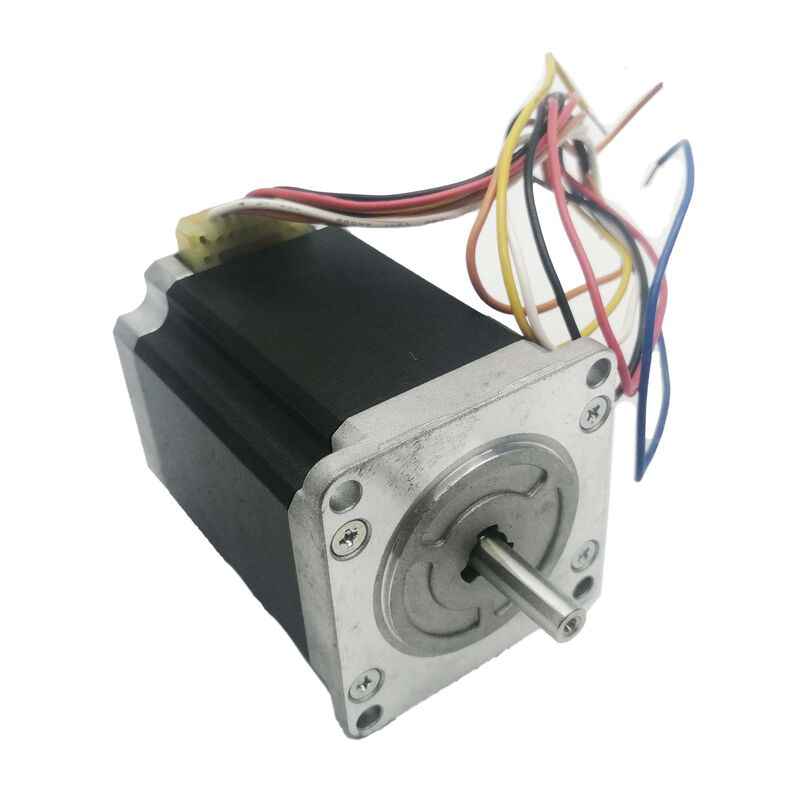
The Sanyo Denki 103H7126-0740 is a 2-phase hybrid stepping motor from the SANMOTION F2 series, producing 1.27 Nm holding torque at 3A/phase on a 24V DC supply. The 1.8° step angle delivers 200 discrete positions per revolution — precise, repeatable positioning without an encoder, driven open-loop through a standard stepper driver at a fraction of the cost and complexity of a closed-loop servo system.
At 56 × 56 mm square flange and 75.8 mm length, this is a well-proportioned mid-range stepping motor: substantial enough in its 1.27 Nm holding torque to handle the loads typical of precision positioning stages, linear actuator drives, conveyor indexing systems, and small CNC machines, while compact enough at 0.98 kg to fit the space constraints these applications commonly impose. The NEMA 23 equivalent footprint is one of the most widely standardised mechanical interfaces in industrial automation, which means the 103H7126-0740 slots into machinery designed for this frame class without custom mounting hardware.
The unipolar 6-wire configuration is the defining electrical characteristic of this particular variant. Unipolar drivers are simpler in circuit design than bipolar H-bridge drivers — the motor's centre-tapped windings allow current to flow through each half-winding alternately without the full bridge switching that bipolar drives require. For system designers specifying a drive alongside this motor, the unipolar option reduces driver complexity and cost; for systems with an existing unipolar drive infrastructure, the 103H7126-0740 matches directly without modification.
Key Specifications
| Parameter |
Value |
| Step Angle |
1.8° (200 steps/revolution) |
| Holding Torque |
1.27 Nm |
| Rated Current |
3 A/phase |
| Supply Voltage |
24V DC |
| Resistance per Phase |
0.9 Ω |
| Rotor Inertia |
0.36 × 10⁻⁴ kg·m² |
| Wiring |
Unipolar, 6-wire |
| Connection Type |
Lead Wire |
| Frame Size |
56 × 56 mm |
| Motor Length |
75.8 mm |
| Shaft Diameter |
6.35 mm |
| Shaft Configuration |
Single, Circular |
| Motor Mass |
0.98 kg |
| Ingress Protection |
IP40 |
| Operating Temperature |
-10°C to +50°C |
| Humidity |
20–90% RH (non-condensing) |
| Compliance |
RoHS, CE, UL, TÜV |
1.8° Step Angle — 200 Steps, Open-Loop Precision
The 1.8° step angle is the standard for 2-phase hybrid stepping motors at this frame size. Each electrical step advances the rotor by exactly 1.8°, producing 200 steps per mechanical revolution. Without any encoder, the motor faithfully executes each step command within its mechanical tolerance, accumulating position from the starting reference purely by counting steps.
This open-loop capability is the economic argument for stepping motors over servo motors in the appropriate application range. A servo motor requires an encoder, a servo drive with closed-loop feedback processing, and the associated wiring and parameter setup. A stepping motor requires a drive that counts steps — straightforwardly less hardware and software complexity for applications where the load is predictable, the step loss risk is low, and the positioning accuracy of ±1.8° (or better with microstepping) meets the specification.
For applications that require finer positioning resolution than full-step 1.8° provides, microstepping — available on compatible drivers — electronically subdivides each step into smaller angular increments. Common microstepping ratios for this motor class are 1/2 step (0.9°), 1/4 step (0.45°), 1/8 step (0.225°), and up to 1/256 step at the finest setting. Higher microstepping ratios improve positional resolution and reduce low-speed torque ripple, at the cost of reduced torque per microstep compared to full-step operation. The 103H7126-0740's rotor inertia of 0.36 × 10⁻⁴ kg·m² is low enough to follow microstepped commands smoothly at moderate speeds.
1.27 Nm Holding Torque — The Static and Dynamic Context
The 1.27 Nm holding torque is the force the motor exerts to resist shaft rotation when the windings are energised and the rotor is stationary at a step position. This is the maximum torque the motor can hold before the rotor steps unintentionally — the detent against which the mechanical load acts when the motor is at rest.
In operation, the available torque is lower than the holding torque and falls further as speed increases. The torque-speed curve of a hybrid stepping motor decreases from the holding torque value at zero speed, through a moderate decline at low speeds, to a steeper falloff at high speeds as the winding inductance limits current rise time within each step. The 0.9 Ω per phase resistance and the inductance characteristics of this motor determine the shape of that curve: at 24V supply and 3A rated current, the motor delivers useful torque across its operating speed range with a 24V driver, though higher supply voltages (through constant-current drives) extend the high-speed torque capability further.
For load sizing, the working torque required — accounting for friction, inertia during acceleration, and any static load opposing the motor — must be less than the available torque at the operating speed by an adequate safety margin. Sanyo Denki's general guidance for stepping systems recommends operating at 50% or less of the available torque at the working speed to provide a reliable margin against missed steps under variable loading conditions.
Unipolar 6-Wire Configuration — Circuit Simplicity and Driver Compatibility
The 103H7126-0740 carries six lead wires from the motor body: two phase windings, each centre-tapped, giving two wires per phase end and one centre-tap per phase. In unipolar operation, the driver switches current through each half-winding in sequence by alternately energising the top and bottom halves of each phase winding while the centre tap is connected to the supply. The H-bridge circuit required for bipolar full-winding operation is not needed — the unipolar switching circuit is a simpler arrangement of transistors or MOSFETs.
The practical consequence: unipolar driver circuits are less expensive and easier to design than bipolar H-bridge drivers. For applications where the drive hardware is custom-designed or where cost is a priority at the driver level, the unipolar motor configuration reduces the driver BOM. For applications using off-the-shelf stepper driver modules, many standard industrial stepper drivers support both unipolar and bipolar operation, often via wiring configuration rather than hardware change.
The 6-wire lead wire connection exits the motor body directly as bare leads, without a connector housing. The installation requires either direct solder connection, crimp termination, or fitting with a connector appropriate to the application's wiring standard. This is the standard connection approach for this motor class in industrial equipment where the connection is made once during machine assembly and the leads are routed through cable management to the driver.
56 × 56 mm Frame — SANMOTION F2 in the Mechanical Context
The 56 × 56 mm square flange is a globally standardised mechanical interface for this class of stepping motor — equivalent to the NEMA 23 mounting standard used widely in North American equipment and adopted broadly in industrial automation worldwide. The bolt circle, register boss, and shaft diameter are consistent with this standard, which means the 103H7126-0740 is a direct physical replacement for any NEMA 23 equivalent motor from other manufacturers, provided the shaft diameter (6.35 mm) and length (approximately 20 mm) match the machine's coupling requirements.
At 75.8 mm body length, this is a full-depth motor in the 56 mm frame class — longer and correspondingly higher in torque than the shorter stack-length variants in the same series (which are typically 45–55 mm in body length at lower torque ratings). The 75.8 mm depth must be confirmed against the machine's motor cavity before ordering, particularly on retrofits where the original motor may have been a shorter-stack variant.
The IP40 protection rating — touchproof and protected against solid objects over 1 mm — suits the clean to lightly contaminated environments where precision positioning equipment operates: enclosed machine cabinets, laboratory automation, semiconductor handling, and electronics manufacturing. For applications with significant dust or fluid exposure, the motor requires an additional protective enclosure around the motor body.
SANMOTION F2 — Sanyo Denki's 2-Phase Hybrid Series
The SANMOTION F2 designation places the 103H7126-0740 within Sanyo Denki's precision hybrid stepping motor range. The hybrid construction — combining the permanent magnet of a PM stepper with the toothed rotor of a variable reluctance motor — is the dominant technology for precision open-loop positioning at this torque and speed class. The hybrid design produces higher torque per unit volume, better step angle accuracy, and more consistent holding torque across rotor positions than earlier PM stepping motor designs.
Sanyo Denki manufactures the SANMOTION F2 series to CE, UL, and TÜV certifications with RoHS compliance, covering the regulatory requirements for industrial equipment sold into European, North American, and Asian markets. The certifications confirm both electrical safety (dielectric strength, insulation resistance) and compliance with the material restriction directives applicable to the motor's construction.
The operating temperature range of -10°C to +50°C is broader than the 0–40°C range typical of servo motor specifications, reflecting the stepping motor's simpler thermal management. Without electronic feedback or encoder circuitry inside the motor body, the 103H7126-0740 tolerates the lower end of the industrial temperature range without the risk of electronic component damage that limits enclosed feedback devices.
FAQ
Q1: Can the 103H7126-0740 be driven as a bipolar motor instead of unipolar?
Yes, with wiring modification. The 6-wire unipolar motor can be wired in bipolar series or bipolar parallel configurations by using the appropriate wire pairs and leaving the centre-tap leads either open (series) or connected as per the bipolar parallel wiring scheme. Bipolar series wiring uses both halves of each winding in series, increasing torque at low speeds but reducing high-speed performance. Bipolar parallel wiring halves the effective resistance and inductance per phase, improving high-speed torque at the cost of requiring a driver capable of handling the doubled current. The motor's rated current of 3A/phase applies to the unipolar configuration; bipolar wiring changes the effective current and voltage requirements and must be recalculated against the driver specification.
Q2: What driver current and voltage should be used with the 103H7126-0740?
The rated current is 3A/phase with 0.9Ω phase resistance. A constant-current chopper driver set to 3A/phase is the standard configuration. The supply voltage should be significantly higher than the motor's resistive drop (3A × 0.9Ω = 2.7V per phase at rated current) to allow the driver's current regulation to function effectively — a 24V supply is the rated voltage and provides adequate current rise speed for moderate operating speeds. Higher supply voltages (up to the driver's maximum) improve high-speed torque by allowing faster current rise within each step period, but require a constant-current driver that regulates the phase current back to 3A regardless of supply voltage. Operating the motor with a supply voltage that drives unregulated current above 3A/phase will cause overheating.
Q3: Does the 1.8° step angle mean the motor always positions accurately to ±1.8°?
The 1.8° is the commanded step increment, not the guaranteed accuracy. Hybrid stepping motors have a typical step accuracy of ±3 to ±5% of one step, non-cumulative — for a 1.8° step, this means approximately ±0.054° to ±0.09° per step, and the error does not accumulate over multiple steps (the position error at any step is independent of the error at the previous step). Full-step accuracy is adequate for most industrial positioning applications. For applications requiring better angular accuracy — semiconductor handling, optical instrument positioning — microstepping and mechanical lead screw or belt transmission geometry further reduce the effective positional uncertainty at the working surface.
Q4: What is the maximum operating speed for the 103H7126-0740?
Sanyo Denki does not publish a single maximum speed figure for the SANMOTION F2 series because usable speed depends on the available torque at that speed, which in turn depends on the driver supply voltage and current regulation. As a general reference, 2-phase hybrid motors of this class at 24V unipolar operation typically deliver useful torque up to approximately 500–1,000 steps/second (150–300 RPM) before torque falls below the load requirement for many positioning applications. With a higher supply voltage constant-current driver, usable speed extends significantly. The correct approach is to plot the motor's torque-speed curve under the actual driver conditions and confirm the available torque exceeds the load torque requirement at the maximum working speed with the 50% safety margin.
Q5: What are the main failure modes to check when evaluating a used 103H7126-0740?
Measure phase-to-phase resistance and phase-to-ground resistance. Each phase pair (end-to-end across a full winding) should read approximately 1.8Ω (2 × 0.9Ω); centre-tap to each end should read approximately 0.9Ω. Significant deviation indicates winding damage or an open circuit. Check insulation resistance between any winding terminal and the motor body with a megger — values below 100MΩ indicate insulation degradation. Rotate the shaft by hand to confirm smooth bearing operation with no roughness or axial play. Confirm the lead wires are intact with no fraying or damage at the strain relief point where the wires exit the motor body — wire fatigue at this point is the most common mechanical failure on motors that have been in service.

 Your message must be between 20-3,000 characters!