Q2HB44MA | 2-Phase Hybrid Stepper Motor Driver — DC 12–40V / 0.5–4A / Up to 200 Subdivisions / 200kpps
Smooth, Low-Noise Stepper Control from a Compact Driver
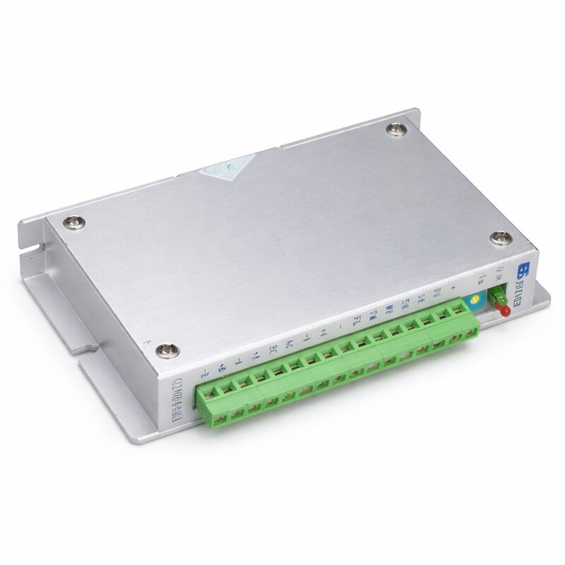
The Q2HB44MA is a constant-torque microstepping driver for 2-phase hybrid stepper motors. Its bipolar constant-current chopping circuit keeps phase current regulated throughout the full speed range. The result is noticeably smoother motor rotation and lower acoustic noise compared to basic step/direction drivers — particularly relevant at mid-range speeds where conventional drivers often produce resonance.
Phase current is continuously adjustable from 0.5A to 4.0A via the onboard switches. The driver accepts motors from 42mm to 86mm in diameter (NEMA 17, 23, and 34 frame classes), covering the majority of 2-phase hybrid stepper motors used in small-format CNC equipment.
A special internal control circuit reduces driver heating by approximately 50% compared to standard bipolar chopping designs and improves high-speed torque output by approximately 30%. When the pulse input stops for more than 100ms, the driver automatically reduces winding current to roughly half the set value, reducing standstill heating in the motor.
Key Specifications
| Parameter |
Value |
| Input Voltage |
DC 12–40V |
| Output Current |
0.5–4.0A per phase |
| Max Subdivision |
200 steps |
| Subdivision Settings |
12/8-gear selection |
| Max Response Frequency |
200 kpps |
| Compatible Motor |
2-phase hybrid, 6/8-lead |
| Motor Diameter |
42–86mm |
| Signal Input |
Opto-isolated, 5V logic |
| Auto Half-Current |
100ms after last pulse |
| Overheat Protection |
Activates at 70°C, resets at 50°C |
| Control Circuit |
Bipolar constant current chopping |
Subdivision and Signal Interface
Subdivision steps are selected via the onboard DIP switches with 12 or 8 fixed gear positions up to 200 subdivisions. Higher subdivision settings produce finer angular resolution per pulse and smoother motion at the cost of requiring more pulses for a given move.
Signal inputs are opto-isolated at 5V logic level. If the controller signal voltage exceeds 5V, add a current-limiting resistor in series with the signal line before connecting. Do not exceed DC 40V on the power supply — reverse polarity is not protected against and will damage the driver.
FAQ
Q1: What motors can the Q2HB44MA drive?
Two-phase hybrid stepper motors with 6 or 8 leads, rated current at or below 4A, and outside diameter between 42mm and 86mm. Four-lead motors are not supported — the internal control circuit requires a 6-lead or 8-lead motor to function correctly.
Q2: How is the output current set?
Via the onboard DIP switches. Drive current is adjustable from 0.5A to 4.0A per phase in steps defined by the switch combination. Set the current to match the motor's rated phase current — exceeding the rated current increases torque temporarily but causes excessive motor heating and shortens motor life.
Q3: The motor runs roughly at certain speeds. What should be checked?
Check the subdivision setting. Too low a subdivision value (such as full or half step) increases the tendency for mid-range resonance. Increase the subdivision to 8× or higher and verify the pulse frequency from the controller is within the 200kpps limit. Also confirm the motor's phase resistance and inductance are within the driver's range.
Q4: Does the Q2HB44MA require an external power supply, and what is recommended?
Yes — a separate DC power supply is required. The recommended range is 12–40V DC. For a 42–57mm motor, 24V DC is typically sufficient. For 57–86mm motors, 36–40V DC is recommended to maintain adequate torque at higher speeds. Use a regulated supply; unregulated supplies can peak above 40V under light load and damage the driver.
Q5: What happens when the overheat indicator turns on?
The driver stops switching and the motor holds its position (if stationary) or the motion stops. The driver resumes automatically when its temperature drops to 50°C. Repeated overheat events indicate inadequate heat dissipation — mount the driver on a metal panel, improve cabinet airflow, or add a small heatsink to the driver body.

 Your message must be between 20-3,000 characters!