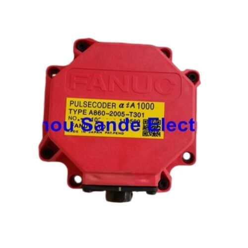
FANUC A860-2005-T301 Pulsecoder — αiI1000 Incremental Encoder for FANUC Alpha i Series Servo Motors
Brand: FANUC
Type: Servo Motor Pulsecoder (Encoder)
Designation: αiI1000
Part Numbers: A860-2005-T301 / A8602005T301
Condition: New | In Stock
When the Machine Stops Trusting Its Own Position
A CNC machine tool's accuracy depends entirely on one thing: the servo system always knowing exactly where each axis is. The motor provides the force. The amplifier provides the current. But it is the pulsecoder — the encoder mounted to the rear of the servo motor — that makes closed-loop position control possible at all. Without reliable feedback from the pulsecoder, the controller is operating blind.
The FANUC A860-2005-T301 is the αiI1000-type pulsecoder fitted to FANUC Alpha i series AC servo motors across a wide range of machine tool and automation applications. It is an incremental optical encoder, mounted directly to the motor's rear endbell, turning with the motor shaft and transmitting high-resolution position and speed signals to the servo amplifier on every revolution. One million pulses per revolution. Compact, sealed construction. Designed specifically for the FANUC αi servo ecosystem.
When this encoder fails — and encoder alarms are among the more disruptive faults in any FANUC-controlled machine — the part that restores the machine to service is exactly this: the correct A860-2005-T301, matched to the motor by its label part number, installed with the correct procedure.
What This Part Is and What It Does
The A860-2005-T301 belongs to FANUC's αiI (Alpha i Incremental) pulsecoder series. It is a built-in encoder — factory-installed inside the motor's endbell housing — rather than an external rotary encoder mounted on a separate shaft. The pulsecoder mounts to the rear of the motor, mechanically coupled to the rotor through an Oldham's coupling that transmits rotational motion while tolerating minor axial and radial misalignment.
The "1000" in the αiI1000 designation refers to the pulsecoder's resolution: 1,000,000 pulses per revolution. At every rotation of the motor shaft, the encoder generates one million discrete feedback signals. The FANUC servo amplifier uses these signals continuously — computing position, velocity, and acceleration to drive the motor precisely according to the CNC controller's commanded trajectory.
The "I" designation — incremental — distinguishes this pulsecoder from the αiA (absolute) variants in the same family. An incremental pulsecoder counts position relative to a reference established at startup. An absolute encoder retains position through power-off cycles. Which type a motor carries is fixed at the factory and cannot be changed by encoder substitution alone — the pulsecoder type must match the motor's original specification, which is why installation always begins with reading the encoder label on the motor being serviced.
Technical Reference
| Parameter |
Value |
| FANUC Part Number |
A860-2005-T301 |
| Pulsecoder Designation |
αiI1000 (Alpha i Incremental 1000) |
| Type |
Incremental optical pulsecoder |
| Resolution |
1,000,000 pulses per revolution |
| Connector |
10-pin |
| Compatible Motor Series |
FANUC Alpha i AC Servo Motors |
| Compatible Motor Range |
αi4 through αi100 (200V and 400V class) |
| Mounting Location |
Motor rear endbell (built-in) |
| Mechanical Coupling |
Oldham's coupling |
| Mounting Hardware |
4× M4 hexagonal socket head bolts |
| Operating Environment |
Enclosed within motor endbell |
| Origin |
Japan |
| Application |
CNC machine tools, industrial automation |
Technical data sourced from FANUC AC Servo Motor αi Series Descriptions (FANUC Manual B-65262EN) and verified supplier documentation.
αiI vs αiA — Getting the Type Right Before You Order
This is the most consequential selection decision when sourcing a replacement A860 series pulsecoder, and it is also the most straightforward to verify correctly.
The A860-2005-T301 is the incremental type (αiI). Its counterpart, the A860-2000-T301, is the absolute type (αiA). Both are 1,000-resolution-class pulsecoders that look physically similar and fit the same motor endbell. They are not interchangeable — the servo amplifier and controller parameters are configured for either incremental or absolute feedback from the factory, and swapping one type for the other will produce errors that prevent the axis from functioning, even if the encoder physically fits.
The correct approach is simple: read the part number printed on the label of the encoder currently in the motor. That label number is the number to match. If the label reads A860-2005-T301, this listing is the correct replacement. If it reads A860-2000-T301 or any other variant, a different part is required.
The same principle applies to the -T301 suffix. Within the A860-2005 series, the T301 is the standard designation for this encoder configuration. Other suffixes exist within the broader FANUC pulsecoder family and carry different connector or specification details. Always match the full part number from the motor label, not just the base number.
Compatible FANUC Alpha i Servo Motors
The A860-2005-T301 is the fitted pulsecoder for FANUC Alpha i series servo motors covering a substantial range of frame sizes and power ratings. Based on verified technical documentation, this encoder is used across:
| Motor Models |
Notes |
| αi4 through αi100 |
Standard 200V AC class |
| αi4 through αi100 (HV) |
400V class high-voltage variants |
| Speed variants |
3,000 r/min to 6,000 r/min ratings |
The αiI1000 pulsecoder spans this range of motor sizes because FANUC standardized the feedback component across the Alpha i platform wherever the 1,000,000 ppr incremental encoder specification applies. The motor frame and power rating determine the amplifier and power section — the pulsecoder is the same part across all compatible models within this range.
For machines using FANUC 0i, 16i, 18i, 21i, 30i, 31i, or 32i CNC controllers with Alpha i series servo motors, the A860-2005-T301 is one of the most frequently required maintenance encoder parts in the installed base.
Replacing This Pulsecoder — What the Procedure Involves
FANUC's own servo motor instruction documentation describes the replacement procedure for built-in pulsecoders. The key steps are consistent across the Alpha i motor range:
The pulsecoder is secured by four M4 hexagonal socket head bolts at the motor endbell. These are the bolts to remove — the M3 bolts located near each M4 bolt are motor assembly fasteners and must not be loosened during this procedure. Removing the wrong bolts can compromise the motor's internal assembly and create additional damage beyond the original encoder fault.
Once the four M4 bolts are removed, the pulsecoder and Oldham's coupling are extracted together. The new pulsecoder is installed with a new Oldham's coupling, positioned with correct orientation so the drive teeth engage properly. The pulsecoder is pushed in until the O-ring on the pulsecoder body seats correctly between the motor pocket and pulsecoder pocket. The O-ring must not be trapped or pinched — a leaking or damaged O-ring compromises the environmental sealing of the motor endbell.
Two handling requirements are stated explicitly in FANUC's documentation: the pulsecoder must not receive mechanical shock during handling or installation, and it must be kept away from dust and cutting chips. As precision optical devices, pulsecoders are more sensitive to physical impact and contamination than the motor itself. Transport in the original packaging until the moment of installation.
The FANUC Alpha i Pulsecoder Family — Where This Part Fits
Understanding where the A860-2005-T301 sits within the broader A860 pulsecoder series helps avoid ordering the wrong part and clarifies what the part number structure means:
| Part Number |
Type |
Designation |
Resolution |
| A860-2000-T301 |
Absolute |
αiA1000 |
1,000,000 ppr |
| A860-2005-T301 |
Incremental |
αiI1000 |
1,000,000 ppr |
| A860-2001-T301 |
Absolute |
αiA16000 |
16,000,000 ppr |
| A860-2010-T301 |
Absolute |
αi-AB128 |
128-division |
The A860-2005-T301 and A860-2000-T301 share the same 1,000,000 ppr resolution but differ in type (incremental vs. absolute). The A860-2001-T301 is a separate high-resolution absolute encoder with 16 million pulses per revolution — a different product for different motor specifications. None of these are interchangeable without corresponding changes to the servo amplifier and controller configuration.
Counterfeit Risk and Sourcing Quality
FANUC pulsecoder counterfeiting is a documented problem in the industrial spare parts market. Non-genuine encoders typically fail quickly because they cannot replicate the optical precision and signal integrity of genuine FANUC-manufactured units — and some never function correctly at all, producing persistent alarm codes that cannot be cleared regardless of parameter adjustments.
Counterfeit encoders are most common through unverified online channels and in markets where the original FANUC part is difficult to source locally. Visual identification of a counterfeit is not always possible from physical inspection alone — counterfeit units frequently copy the external appearance and labeling of genuine parts.
The protection against this risk is sourcing from suppliers who handle verified stock with documented origin and who take accountability for the part's authenticity. This listing provides genuine FANUC manufacture. If there is ever doubt about the part received, the FANUC serial number and manufacturing markings on the encoder label can be cross-referenced against known-genuine examples before installation.
FAQ
Q1: My machine is showing a FANUC encoder alarm. How do I determine whether the A860-2005-T301 pulsecoder is actually the cause, rather than the encoder cable or amplifier?
FANUC servo alarms related to the encoder typically fall into a few categories, and isolating the component at fault before ordering parts avoids an unnecessary replacement. Start by inspecting the encoder cable — the cable connecting the motor pulsecoder to the servo amplifier's CN2 port — for visible damage, bent or corroded pins, or a loose connection at either end. A damaged cable is a common cause of encoder alarms and is less expensive to replace than the pulsecoder itself. If the cable is intact, swap the suspect axis's encoder cable with a known-good cable from another axis on the same machine (assuming the same cable type is used) and observe whether the alarm follows the cable or stays with the motor. If the alarm stays with the motor regardless of cable, the pulsecoder itself is the likely fault. FANUC alarm codes in the 300-series and SV alarm categories specific to feedback signal abnormalities are typical indicators of pulsecoder failure, though a FANUC technical reference or your machine documentation will provide the exact alarm number interpretation for your controller model.
Q2: Can the A860-2005-T301 be replaced with the A860-2000-T301 absolute encoder if the incremental version is unavailable?
No — these two encoders are not interchangeable, despite sharing the same 1,000,000 ppr resolution class. The αiI (incremental) and αiA (absolute) designations reflect a fundamental difference in how the encoder communicates position to the servo amplifier and controller. An absolute pulsecoder continuously provides a full position address to the amplifier and retains position through power cycles. An incremental pulsecoder counts from a reset reference and requires re-referencing after each power cycle. The servo amplifier's internal firmware, and the CNC controller's axis parameters, are configured at setup for either incremental or absolute feedback from each axis. Installing an absolute encoder on an axis configured for incremental feedback — or vice versa — will generate amplifier alarms that prevent axis operation, and in some configurations may produce incorrect position data without an alarm. The replacement encoder type must match the original.
Q3: Does replacing the pulsecoder require any parameter changes or controller re-initialization after installation?
For a direct replacement of a failed A860-2005-T301 with an identical A860-2005-T301 on the same axis, no parameter changes are required provided the replacement is the same pulsecoder type and the mechanical installation is correct. The servo amplifier and CNC controller parameters that govern encoder type and resolution were set during the machine's original commissioning and remain stored in the controller's non-volatile memory. Since the replacement encoder is identical in specification to the one removed, those parameters remain valid. What may be required after installation — depending on the machine's referencing mode — is re-establishing the machine's reference point (zero return or home position), because an incremental encoder does not retain absolute position through replacement. Follow the machine builder's procedure for reference position establishment after maintenance that involves encoder replacement.
Q4: The Oldham's coupling is mentioned in the replacement procedure. Should the coupling always be replaced at the same time as the pulsecoder?
FANUC's service documentation recommends installing a new Oldham's coupling together with the new pulsecoder during encoder replacement. The Oldham's coupling is the flexible mechanical interface between the motor shaft and the pulsecoder's input. Its purpose is to transmit rotation while accommodating small amounts of angular and axial misalignment that would otherwise stress the pulsecoder's internal bearing and optical assembly. A coupling that has been in service for years — particularly in a machine that experienced any bearing wear or vibration — may have developed wear on its drive teeth or hardening of the flexible element material. Installing a new encoder on a worn coupling transfers that wear-induced misalignment directly to the new pulsecoder, potentially shortening its service life. Replacing the coupling is low-cost insurance that protects the encoder investment.
Q5: This encoder is listed as an incremental type. Does that mean the machine must perform a reference return every time it is powered on?
Yes, that is the standard operating behavior for machines using incremental pulsecoders. Because the A860-2005-T301 αiI type encoder counts position from a reset reference rather than retaining an absolute position address, the servo system does not know the axis's absolute position at power-on. Before the CNC can execute a machining program, each axis must perform a reference return (also called zero return or home return depending on machine builder terminology) to establish the position reference. This is built into the normal power-on sequence for any machine equipped with incremental feedback. It is not a fault condition — it is the designed operating mode. Machines where eliminating the homing sequence is operationally important are typically equipped with the αiA (absolute) type pulsecoder instead, which retains position through power cycles and allows immediate axis operation after power-on without a reference return.

 Your message must be between 20-3,000 characters!