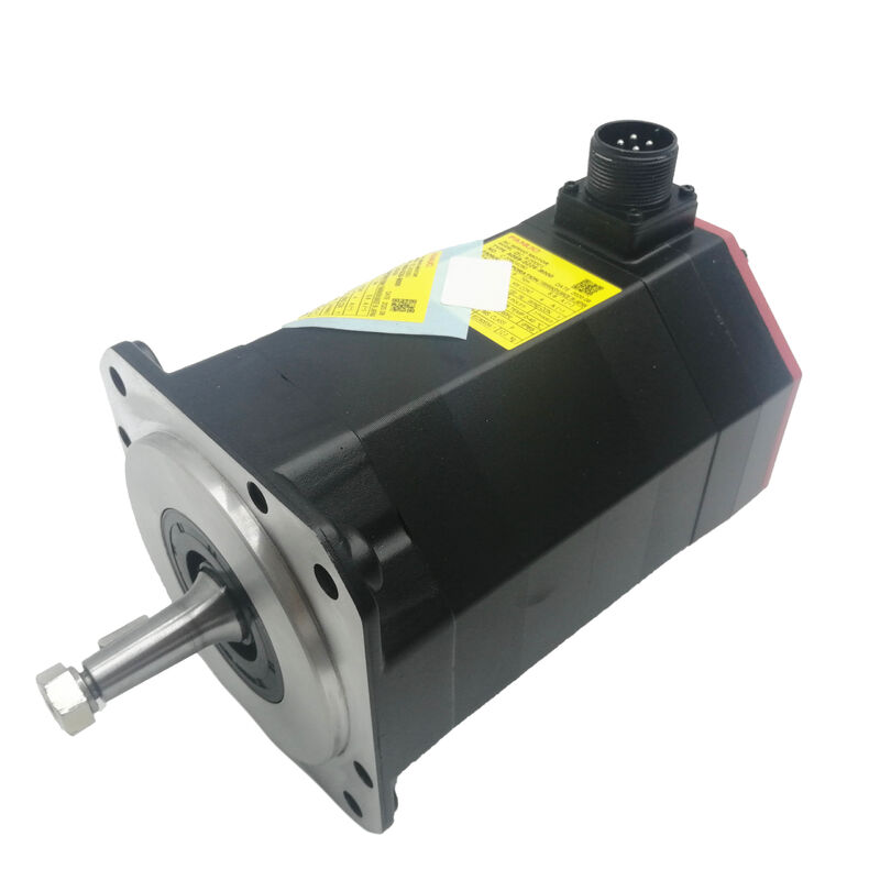
Fanuc A06B-0229-B300 AC Servo Motor — αiF 8/3000HV, Taper Shaft, 24V Brake, A1000 Absolute
Product Overview
Part Number: A06B-0229-B300
Also Searched As: A06B0229B300, FANUC A06B-0229-B300, Fanuc A06B0229B300
Motor Model: αiF 8/3000HV (Alpha iF 8/3000 High Voltage)
Classification: Fanuc Alpha iF Series High-Voltage AC Brushless Servo Motor — 8 Nm Stall Torque, 3,000 rpm, Taper Shaft with Key, 24V Spring-Applied Brake, Alpha i A1000 Absolute Pulse Coder, IP65, 400V Class
Technical Specifications
| Parameter |
Value |
| Part Number |
A06B-0229-B300 |
| Motor Model |
αiF 8/3000HV |
| Rated Output |
1.6 kW |
| Stall Torque |
8 Nm |
| Maximum Speed |
3,000 rpm |
| Motor Input Voltage |
364V AC (3-phase) |
| Frequency Range |
0–200 Hz |
| Amplifier Supply |
400V class (HV series) |
| Pulse Coder |
Alpha i A1000 (serial absolute) |
| Encoder Resolution |
1,000,000 pulses/rev |
| Shaft Type |
Taper with key (TPR) |
| Electromagnetic Brake |
24V spring-applied |
| Protection Rating |
IP65 |
| Insulation Class |
Class F |
| Operating Temperature |
0°C to +40°C |
| Compatible Amplifiers |
Fanuc αi HV series servo amplifiers (αiSV HV) |
| Compatible Controls |
Fanuc Series 0i, 15i, 16i, 18i, 21i, 30i, 31i, 32i |
| Origin |
Japan |
The HV Designation — What It Changes and Why It Matters
Everything in the A06B-0229-B300's part number has a counterpart in the standard 200V αiF family — the same frame, the same stall torque, the same taper shaft and brake configuration. The single letter that changes the whole picture is HV.
HV stands for High Voltage — and in the Fanuc αiF context, it means this motor and its matched amplifier operate from a 400V class power supply rather than the 200V class used by the standard αiF series. The motor input voltage is 364V instead of the ~149–200V range of the standard variants. The amplifier draws from a 400V three-phase supply, steps down internally to the motor's operating voltage, and drives the motor winding through the same servo control architecture as the 200V platform.
The practical reason 400V class systems exist in CNC machine tool designs is infrastructure. A substantial portion of the world's industrial facilities — particularly in Europe and much of Asia — distribute 400V three-phase power to machine tool circuits as standard. Running a 200V class servo system in a 400V plant requires a step-down transformer for the servo supply, adding cost, panel space, and a potential point of failure. The HV motor-and-amplifier platform eliminates that transformer by accepting 400V supply directly.
For the end user replacing a failed A06B-0229-B300, the HV designation creates one non-negotiable constraint: the replacement must also be an HV variant. A standard 200V αiF 8/3000 motor — despite identical torque and speed ratings — cannot be substituted into an HV amplifier system. The motor winding voltage, the amplifier's output voltage, and the system's parameter configuration are all matched to the HV platform. This is not a minor substitution risk; it is a configuration incompatibility that will result in immediate system fault or motor damage.
8 Nm, Taper Shaft, Brake: Three Decisions Embedded in One Part Number
The three defining mechanical and performance characteristics of the A06B-0229-B300 — stall torque, shaft type, and brake — each reflect a specific design choice by the machine builder who specified this motor. All three must be replicated in any like-for-like replacement.
Eight Newton-metres of stall torque places this motor in the productive middle of the αiF HV range. On a 10mm pitch ball screw with 90% efficiency, 8 Nm produces approximately 4.5 kN of continuous axial thrust — the load range of a mid-size CNC machining centre table axis, a lathe carriage drive on a medium turning centre, or a secondary linear axis on a larger multi-axis machine. The 1.6 kW continuous power output provides the sustained cutting performance these axes need over long machining cycles without exceeding the motor's thermal rating.
Taper shaft with key is the machine tool industry's preferred coupling interface for good reason. The taper geometry self-centres the coupling hub during installation — the hub is drawn onto the tapered shaft and the conical contact automatically aligns the hub to the motor shaft axis without manual adjustment. The key transmits torque through positive mechanical engagement. The combination means repeatable coupling geometry across every service event: remove the hub with a puller, fit the new motor, reinstall the hub, and the axis returns to its pre-service geometric relationship with the drive mechanism.
24V spring-applied brake is on this motor because the machine it serves needs it — likely a vertical axis or an inclined feed where gravitational load must be mechanically held at servo-off. The brake engages by spring force when the 24V coil is de-energised, which means power loss of any kind — planned shutdown, E-stop, amplifier fault, mains trip — results in immediate and automatic mechanical shaft holding. No servo lock, no control signal, no logic required. The shaft is held.
The 24V Brake: Spring-Applied, Fail-Safe, Non-Optional on Vertical Axes
The spring-applied brake on the A06B-0229-B300 is worth understanding in engineering terms, not just as a checkbox on a specification sheet. The fail-safe principle — spring on, power off — is foundational to machine safety architecture, and every maintenance decision involving this motor needs to respect it.
Under normal operating conditions, the 24V DC brake coil is energised, compressing the spring and releasing the brake disc. The shaft rotates freely under servo control. At servo-off — whether from a normal power-down sequence, an E-stop command, or an unplanned fault — the brake coil is de-energised as part of the shutdown sequence, the spring engages the disc, and the shaft is mechanically clamped. The CNC does not need to issue a brake command; the brake engages automatically as a consequence of power removal.
For a vertical Z-axis on a machining centre, this means the spindle head assembly — potentially carrying a heavy motorised spindle, toolholder, and any workpiece fixture mass — is mechanically held in place every time the machine powers down, regardless of the reason for shutdown. For an inclined rotary table or a tilting axis, the same principle applies. Servo lock alone cannot provide this guarantee; it requires an active amplifier and a working feedback loop.
When this motor is replaced, the brake wiring and interlock logic must be reconnected correctly before the machine is returned to production. Specifically: verify the brake releases correctly when power is applied, confirm the brake engages correctly when power is removed, and test the axis response to an E-stop event before running any production program. These verification steps take minutes and prevent the failure modes that omitting them creates.
A1000 Absolute Encoder: Position Retained Through Every Power Cycle
The Alpha i A1000 serial absolute pulse coder on the A06B-0229-B300 delivers 1,000,000 pulses per revolution with multi-turn absolute position retained through power-off by the backup battery in the Fanuc αi HV servo amplifier.
The operational benefit is direct: every power-up returns the axis to a known coordinate without any homing movement. On a mid-size machining centre with multiple αiF HV axes, this means the machine is ready to run immediately after power-up — no supervised homing traverse, no waiting for each axis to reach its reference marker, no production delay at every shift start. For machines that experience frequent power cycling or that must recover from alarms quickly, the cumulative time saved by absolute encoder operation is a real productivity figure.
The absolute position is retained by a battery in the servo amplifier, not in the motor. Replace this battery when the Fanuc CNC issues a low battery alarm. A depleted battery resets the multi-turn counter, requiring a one-time axis re-referencing to restore the machine coordinate — a manageable recovery, but entirely avoidable with timely battery maintenance.
At 1,000,000 counts per revolution, the position loop resolution is at the nanometre scale on standard ball screw pitches. This resolution is what gives the CNC the feedback quality it needs to hold tight dimensional tolerances on demanding machining operations while compensating for thermal drift, axis loading, and servo following error in real time.
A06B-0229 Series: Full Configuration Reference
All variants in the A06B-0229 series share the αiF 8/3000HV motor body — 8 Nm stall torque, 3,000 rpm, 364V, A1000 absolute encoder. Shaft type and brake configuration are the differentiating factors.
| Part Number |
Shaft |
Keyway |
Brake |
Sealing |
| A06B-0229-B000 |
Taper |
Yes |
None |
IP65 |
| A06B-0229-B100 |
Straight smooth |
No |
None |
IP65 |
| A06B-0229-B200 |
Straight |
Yes |
None |
IP65 |
| A06B-0229-B300 |
Taper |
Yes |
24V spring |
IP65 |
| A06B-0229-B400 |
Straight smooth |
No |
24V spring |
IP65 |
| A06B-0229-B500 |
Straight |
Yes |
24V spring |
IP65 |
The B300 is the taper-plus-key, braked, standard IP65 baseline for this series — the configuration specified on axes requiring both the geometric repeatability of taper coupling and the mechanical safety of spring-applied holding. Confirm the exact suffix of the failed motor before ordering; the shaft and brake configuration are coupling and safety-critical elements that cannot be substituted between variants without consequence.
Amplifier and CNC Compatibility
The A06B-0229-B300 requires a Fanuc αi HV series servo amplifier (αiSV HV) — the high-voltage variant of the αiSV module, designed to accept 400V three-phase supply and drive the HV motor winding. This is specifically the HV amplifier, not the standard 200V αiSV. The two amplifier variants are not interchangeable, and fitting an HV motor to a standard 200V αiSV amplifier is not possible without a complete drive system reconfiguration.
Compatible CNC platforms include Fanuc Series 0i-D, 0i-F, 15i, 16i, 18i, 21i, 30i-A, 30i-B, 31i-A, 31i-B, and 32i. The CNC communicates with the αiSV HV amplifier through the same FSSB (Fanuc Serial Servo Bus) fibre optic link used across the full αi series — the HV variant is transparent to the CNC at the communication level.
After fitting a replacement motor, verify the CNC axis parameters for motor type, maximum speed, and current limit match the αiF 8/3000HV HV motor specification. Parameter mismatches on an HV system produce the same symptoms as on standard-voltage systems — unstable servo, overcurrent faults, or thermal alarms — but the consequences of running an oversized current limit with an HV motor are more severe because the bus voltage is higher.
Typical Applications
Primary feed axis drives on 400V class CNC machining centres. X, Y, and Z table, saddle, and quill drives on Fanuc αi HV controlled vertical and horizontal machining centres in 400V infrastructure environments, where the HV motor-amplifier system eliminates the step-down transformer requirement.
CNC turning centre carriage and cross-slide drives. Z-axis carriage and X-axis cross-slide drives on medium-format CNC turning centres operating from 400V supply, where the 8 Nm stall torque handles the cutting forces and axis mass of a mid-size turning centre workpiece range.
Vertical axis drives requiring brake. Z-axis and quill feeds on machining centres where the spindle head assembly mass requires mechanical holding at servo-off, and the 24V spring-applied brake on the B300 provides that holding function as a fail-safe mechanical mechanism.
Multi-axis machining centres in European and Asian 400V facilities. Any Fanuc αi HV controlled machining system operating from 400V three-phase supply in manufacturing facilities where 400V infrastructure is standard and the HV servo system was specified to avoid step-down transformer costs.
FAQ
Q1: Why is the HV motor model non-interchangeable with the standard αiF 8/3000 — they have the same torque rating?
Stall torque is the same, but the electrical systems are completely different. The HV motor is wound for 364V input from a 400V class αiSV HV amplifier. The standard αiF 8/3000 motors are wound for ~149–200V from a 200V class αiSV amplifier. Connecting an HV motor to a 200V amplifier produces insufficient torque because the voltage is wrong for the winding. Connecting a standard motor to an HV amplifier risks immediate winding insulation failure. The amplifier, motor, and power supply voltage class must all match. Never substitute across HV and standard variants.
Q2: Can the brake on the B300 be permanently released or bypassed to simplify the wiring?
No — not safely, and not on a vertical or inclined axis. The 24V brake is a safety mechanism, not a convenience feature. On any axis where gravitational load acts along the direction of shaft rotation, the brake is the only thing that holds the axis at servo-off. Bypassing or permanently releasing it means the axis will descend under gravity whenever the servo is inactive — E-stop, amplifier fault, power-down. On a machine where the brake was part of the original safety design, removing its function changes the machine's safety architecture in a way that requires a formal risk assessment, not a wiring shortcut.
Q3: Does the A1000 encoder require a homing cycle on every CNC power-up?
No. The Alpha i A1000 is a serial absolute encoder that retains multi-turn shaft position through power-off via the backup battery in the αiSV HV amplifier. When the CNC powers up, the axis coordinate is immediately available — no reference-return traverse is required under normal operating conditions. The one exception: if the backup battery depletes fully, the multi-turn counter resets and a one-time re-referencing is needed. Replace the battery when the CNC issues a battery alarm to avoid this.
Q4: What αiSV HV amplifier module is needed for the A06B-0229-B300?
The motor requires a Fanuc αi HV series servo amplifier (αiSV HV) — specifically the module rated for the αiF 8/3000HV motor's current class. The exact αiSV HV module designation should be confirmed from the machine's electrical documentation or original drive cabinet specification, as multiple current ratings exist in the HV amplifier range. The αiSV HV accepts 400V three-phase supply directly. Standard αiSV amplifiers designed for 200V supply are not compatible with this motor.
Q5: The B300 uses a taper shaft — what is the correct procedure for removing the coupling hub during motor replacement?
The taper shaft coupling hub must be removed with a proper gear puller — specifically a puller that applies extraction force against the hub face while reacting against the shaft end. Never use wedges, chisels, or impact against the hub body to free it from the taper; these methods damage the hub bore or shaft taper geometry, compromising future coupling engagement. Thread the draw bolt out of the shaft end to clear it, engage the puller legs behind the hub face, and apply steady extraction force. Once freed, inspect the taper and bore surfaces for fretting or mechanical damage before refitting. Install the hub on the new motor shaft with the key engaged, draw to the correct axial position using the draw bolt torqued to the coupling manufacturer's specification, and verify the hub seats correctly before reconnecting the drive train.

 Your message must be between 20-3,000 characters!