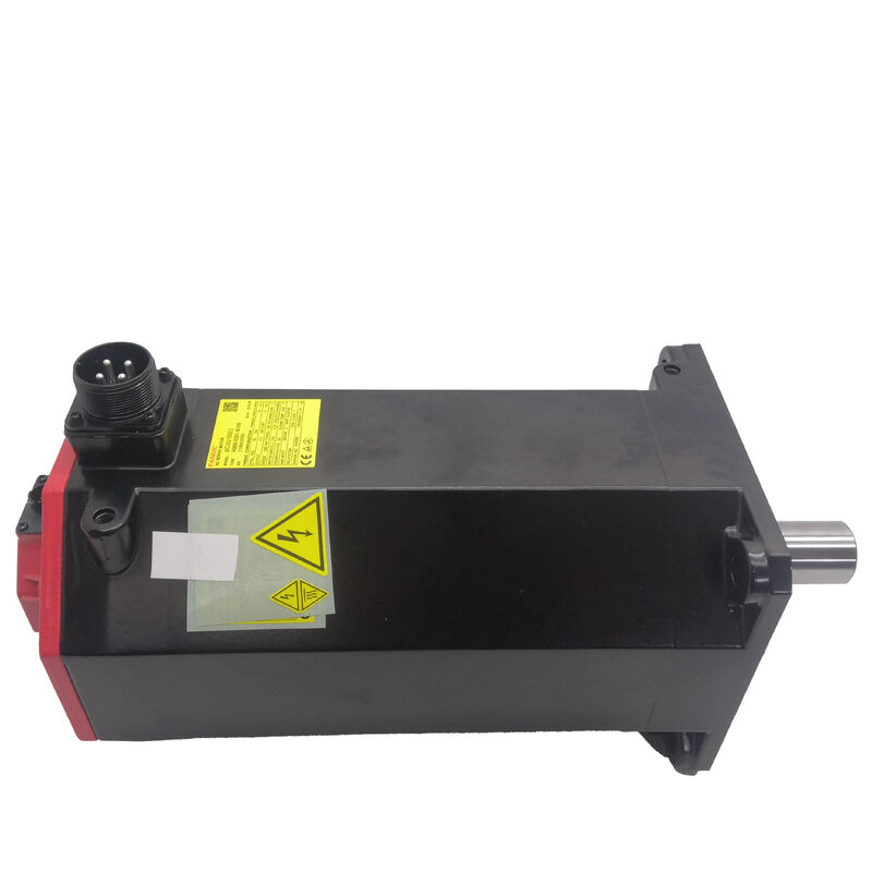
Part Number: A06B-0253-B400
Also Searched As: A06B0253B400, FANUC A06B-0253-B400, Fanuc A06B0253B400
Motor Model: αiF 30/4000
Classification: Fanuc Alpha iF Series AC Brushless Servo Motor — 30 Nm Stall Torque, 4,000 rpm Maximum Speed, Straight Smooth Shaft, 24V Spring-Applied Brake, Alpha i A1000 Absolute Pulse Coder, IP65
| Parameter | Value |
|---|---|
| Part Number | A06B-0253-B400 |
| Motor Model | αiF 30/4000 |
| Stall Torque | 30 Nm |
| Peak Torque | 40 Nm |
| Maximum Speed | 4,000 rpm |
| Phases | 3-phase |
| Pulse Coder | Alpha i A1000 (serial absolute) |
| Encoder Resolution | 1,000,000 pulses/rev |
| Shaft Type | Straight smooth (SLK — no keyway) |
| Electromagnetic Brake | 24V spring-applied |
| Sealing | IP65 (standard) |
| Insulation Class | Class F |
| Operating Temperature | 0°C to +40°C |
| Compatible Amplifiers | Fanuc αi series servo amplifiers (αiSV) |
| Compatible Controls | Fanuc Series 0i, 15i, 16i, 18i, 21i, 30i, 31i, 32i |
| Shipping | Freight required (large frame) |
| Origin | Japan |
Position the A06B-0253-B400 correctly in the Fanuc αiF servo motor family and its role becomes immediately clear. Thirty Newton-metres of continuous stall torque and 40 Nm available during acceleration transients place this motor at the high end of the αiF range — designed not for lightweight positioning axes or compact auxiliary drives, but for the heavy primary feed axes of large-format CNC machine tools where sustained torque under cutting load is the governing design requirement.
Think about what 30 Nm of stall torque means in a real machining application. On a 16mm pitch ball screw with 90% efficiency, this motor sustains over 10 kN of continuous axial thrust. That is the load range of a saddle drive on a large horizontal machining centre carrying a substantial workpiece pallet, a table drive on a heavy vertical machining centre, or a cross-slide axis on a large CNC turning centre handling metre-diameter forgings. The αiF 30/4000 was sized for these machines specifically — axes where smaller motors would saturate current limits under heavy cutting load and compromise positioning accuracy and surface finish on demanding operations.
The 40 Nm peak torque figure adds a further dimension. During rapid acceleration at the start of a positioning move, the servo loop demands torque well above the continuous rating to bring the axis to commanded velocity in minimum time. The 40 Nm ceiling governs how aggressively the CNC can accelerate the axis on short-stroke positioning moves — a direct factor in cycle time on machining centres where axis reversals and short moves dominate the program. More peak torque available from the motor means the CNC's acceleration time constant can be set shorter without hitting the motor's current limit, which accumulates as real cycle time savings across a production shift.
The B400 suffix confirms a 24V spring-applied electromagnetic brake — and on a motor of this torque class, that brake is carrying a real mechanical safety function that must be understood before specifying any replacement.
Spring-applied brakes operate on the fail-safe principle that mechanical safety systems are built around. When electrical power is present and applied to the brake coil, an electromagnetic force compresses the spring and releases the brake disc — the shaft is free to rotate under servo control. When electrical power is removed, for any reason — controlled shutdown, E-stop actuation, amplifier fault, power interruption — the spring force engages the brake immediately without any control signal required. The shaft is mechanically held.
On a machine where the A06B-0253-B400 drives a vertical axis — a quill axis on a large VMC, a ram drive on a gantry machining centre, or a workpiece table on a vertical turning lathe — gravity acts continuously on the mass of the moving assembly in the direction of shaft rotation. Without the brake engaged at servo-off, that gravitational load would drive the axis downward the moment the amplifier de-energises. The 24V spring brake is what prevents that movement, protects the workpiece and tooling from a falling axis, and allows the machine to shut down safely.
At 30 Nm stall torque, the axis being driven by this motor carries substantial mass. The brake torque specification must be adequate to hold that load against gravity at servo-off — and Fanuc's brake specification for this motor frame is sized accordingly. When specifying a replacement, the brake variant is not optional equipment: a brakeless B000 or B100 motor cannot substitute for a B400 on a vertical axis or any inclined feed axis carrying a gravitational load component.
The straight smooth shaft (SLK — no keyway) on the A06B-0253-B400 raises an important practical point that becomes more critical as torque increases. At 30 Nm stall and 40 Nm peak, the coupling between motor and driven load must be correctly sized and correctly installed to transmit the full torque range without slipping.
Smooth-shaft coupling hubs — split-hub clamp designs or hydraulic expansion hubs — transmit torque entirely through friction between the hub bore and the shaft outer diameter. The clamping force is generated by the hub's clamping screws, and the resulting friction must exceed the peak torque the motor can develop. At 40 Nm peak, the coupling specification for this motor requires careful engineering — a coupling hub that is adequate for 15 or 20 Nm will slip under full acceleration torque from the αiF 30/4000.
For replacement purposes: when this motor is fitted on a machine as a like-for-like replacement, the existing coupling hub on the machine is already sized and installed correctly for the original motor's torque output — provided the coupling was correctly specified and installed when the machine was built. The replacement procedure is straightforward: remove the hub from the old motor shaft using a proper puller, transfer it to the new motor shaft, and retighten the clamping screws to the coupling manufacturer's specified torque value. Do not assume the hub transfers at the same clamping torque — verify the specification.
For installations where the machine design calls for a keyed coupling interface — gear pulleys, precision flange couplings, or any application where a key provides the primary torque transmission path rather than friction — the appropriate variant is the A06B-0253-B100 (straight shaft with keyway, A1000 absolute, no brake) or the taper shaft brake variants within the A06B-0253 series. The shaft type must match the coupling hardware on the machine.
Every A06B-0253-B400 carries the Alpha i A1000 serial absolute pulse coder — 1,000,000 pulses per revolution, multi-turn position retained through power-off by the backup battery in the Fanuc αi servo amplifier.
On a machine with a heavy vertical or inclined axis fitted with this motor, the absolute encoder does more than simplify startup. It provides the CNC with verified axis position the moment power is restored — before any axis movement occurs — which is a meaningful contribution to safe machine recovery after an alarm or power interruption. The CNC knows where the axis is. The brake can be released under servo control. The axis can be moved under CNC command to a safe position. None of this requires a homing traverse that, on a large vertical axis, could be hazardous if the machine's state at power-down was not a clean parked position.
At 1,000,000 counts per revolution on typical large-machine ball screw pitches — 10mm, 16mm, 20mm — the encoder resolution delivers sub-micron position loop closure. That resolution is what allows the CNC to hold a heavy axis against the combined effects of cutting load, gravity, and thermal drift with the repeatability precision machining requires.
Battery maintenance: the A1000 multi-turn counter is retained by a battery in the servo amplifier, not in the motor itself. Replace it when the Fanuc CNC issues a low battery warning alarm. A depleted battery resets the multi-turn position counter and requires a one-time re-referencing of the axis to the machine coordinate system.
The A06B-0253-B400 is a large-frame servo motor. Its physical dimensions and weight require freight carrier shipping — standard parcel carrier services are not applicable. Plan for freight transit time when scheduling installation, and confirm delivery requirements: liftgate service, scheduled delivery appointment, or dock-to-dock freight depending on the receiving location's capabilities.
The A06B-0253 series covers the αiF 30/4000 motor across multiple shaft, brake, and sealing configurations. Matching the correct variant to the machine's existing coupling and safety architecture is essential — particularly on large machines where incorrect brake specification has direct safety implications.
| Part Number | Shaft | Keyway | Brake | Encoder | Sealing |
|---|---|---|---|---|---|
| A06B-0253-B000 | Taper | Yes | None | A1000 absolute | IP65 |
| A06B-0253-B100 | Straight | Yes | None | A1000 absolute | IP65 |
| A06B-0253-B400 | Straight smooth | No | 24V spring | A1000 absolute | IP65 |
| A06B-0253-B400#0100 | Straight smooth | No | 24V spring | A1000 absolute | IP67 |
| A06B-0253-B300 | Taper | Yes | 24V spring | A1000 absolute | IP65 |
The B400 is the straight smooth shaft, braked, standard IP65 configuration. The #0100 sealed variant upgrades to IP67 for high-coolant-exposure environments — required when the motor is mounted in a position where direct coolant splash or wash-down exposure is anticipated.
Primary table and saddle drives on large horizontal machining centres. X and Y axis drives on large-format HMCs where the pallet, workpiece, and fixture mass demands sustained torque output at the 30 Nm stall level, and the brake provides safe holding at servo-off when the axis carries a gravitational load component.
Vertical axis drives on large VMCs and gantry machines. Z-axis quill drives, ram feeds, and headstock vertical slides on large vertical machining centres and gantry-type machines where the brake is a mandatory safety feature for the moving assembly mass.
Heavy turning centre carriage and cross-slide drives. Z-axis carriage and X-axis cross-slide drives on large CNC turning centres handling heavy workpieces, where the cutting force and sustained feed load demand 30 Nm continuous torque and the A1000 absolute encoder provides immediate position recovery after E-stop or alarm events.
Large-format 5-axis machining centre primary feeds. Primary linear axis drives on large 5-axis machining centres for aerospace structural components and large mould and die work, where the axis mass and cutting forces place the motor requirement firmly in the αiF 30/4000 torque range.
Q1: Why is a 24V brake essential on this motor for vertical axis applications — can servo lock substitute?
Servo lock requires the amplifier to be powered and active to hold axis position. Any event that removes amplifier power — E-stop, fault trip, mains interruption, or planned shutdown — immediately removes servo lock, leaving a vertical axis free to move under gravity. On a large axis driven by an αiF 30/4000, the gravitational load is substantial and the descent will be rapid without mechanical holding. The 24V spring-applied brake provides mechanical holding independent of amplifier power — when power is removed, the spring engages the brake automatically. For any axis with a gravitational load component, the brake is not an option; it is the safety mechanism the machine was designed around.
Q2: What is the practical difference between the standard B400 (IP65) and the B400#0100 (IP67) variant?
The base A06B-0253-B400 carries IP65 sealing — protected against dust ingress and directed water jets. The #0100 variant upgrades to IP67 — protected against temporary immersion in water up to 1 metre depth. For most machining centre environments where the motor is mounted away from the direct cutting zone, IP65 is adequate. The IP67 variant is correct for installations where the motor is exposed to direct coolant flood, high-pressure wash-down, or coolant accumulation in the motor mounting area. Specifying the standard B400 in an IP67 environment risks progressive coolant ingress into the motor windings over time.
Q3: Does the A06B-0253-B400 require a homing cycle after every CNC power-up?
No. The Alpha i A1000 is a serial absolute encoder retaining multi-turn shaft position through power-off via the backup battery in the Fanuc αi servo amplifier. The axis coordinate is re-established immediately when the CNC powers up — no reference-return traverse is required. This is operationally significant on large heavy axes where a homing traverse at slow speed covers substantial distance and takes meaningful time. After installing a replacement motor for the first time, a single one-time position synchronisation is required to match the absolute counter to the machine coordinate — this is a standard commissioning step, not a recurring operational requirement.
Q4: This is a large motor — what amplifier does it pair with, and does the shipping size create logistics challenges?
The A06B-0253-B400 requires a Fanuc αi series servo amplifier (αiSV) — the specific αiSV current rating must match the αiF 30/4000 motor's power class; confirm from the machine's drive documentation. Compatible CNCs include Fanuc Series 0i-D/F, 16i, 18i, 21i, 30i, and 31i. On shipping: the motor's frame size requires freight carrier delivery — not parcel carrier. Schedule freight delivery in advance of the maintenance window, confirm whether liftgate or dock service is needed at the receiving location, and allow for freight transit time when planning the motor swap.
Q5: Can the smooth shaft on the B400 be substituted with a keyed shaft version if the machine coupling uses a key?
Not without changing the coupling hardware. The B400 has a straight smooth shaft with no keyway — any coupling hub on the machine must be a smooth-bore clamp type to match. If the existing machine coupling hub has a keyed bore, the correct motor variant is one with a matching keyed shaft — either the A06B-0253-B100 (straight keyed shaft, no brake, A1000) or the A06B-0253-B300 (taper shaft with key, brake, A1000). Fitting a smooth-shaft motor where a keyed hub is installed is not a viable substitution without replacing the coupling hub, and vice versa. Always match the shaft configuration to the existing coupling hardware on the machine.