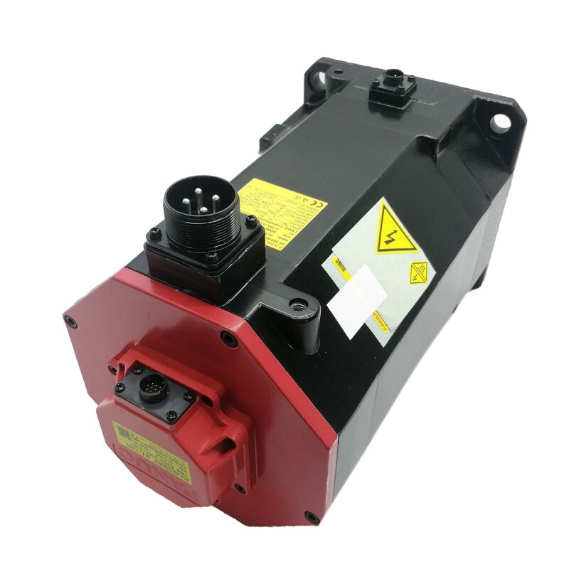
Fanuc A06B-0243-B101 — αiF 12/4000 AC Servo Motor, Straight Shaft, Electromagnetic Brake, Alpha i i1000 Pulse Coder
Product Overview
Part Number: A06B-0243-B101
Also Searched As: A06B0243B101, Fanuc A06B-0243-B101, FANUC A06B0243B101
Motor Model: αiF 12/4000
Classification: Fanuc Alpha iF Series AC Brushless Servo Motor — 3 kW, 4,000 rpm, Straight Smooth Shaft, Electromagnetic Brake, Alpha i i1000 Pulse Coder
What This Motor Is
The Fanuc A06B-0243-B101 is a 3 kW αiF 12/4000 AC servo motor — one of the higher-capacity motors in the Fanuc alpha iF series, configured with a straight smooth shaft, an electromagnetic brake, and the Alpha i i1000 serial pulse coder at 1,000,000 pulses per revolution.
Three specifications define where this motor belongs. The 12 Nm stall torque places it at the top end of the α iF family's mid-capacity range — capable of sustaining substantial axial force on ball-screw axes, heavy radial loads on milling machine table drives, or sustained cutting torque on turning centre carriage axes. The electromagnetic brake, encoded in the B1xx suffix, means this motor is configured for axes where position must be held mechanically when the servo is off — vertical axes, inclined feeds, and any drive where servo lock alone is insufficient. The i1000 pulse coder — the incremental 1,000,000 ppr serial encoder — provides the position resolution and velocity feedback quality that Fanuc's high-accuracy CNC interpolation requires at any feed rate.
Reading these three facts together describes a motor designed for vertical CNC axes on machines equipped with Fanuc αi-series amplifiers and 0i, 30i, or 31i CNC controls.
Technical Specifications
| Parameter |
Value |
| Part Number |
A06B-0243-B101 |
| Motor Model |
αiF 12/4000 |
| Rated Output |
3 kW |
| Supply Voltage |
3-phase 200V AC |
| Rated Speed |
4,000 rpm |
| Stall Torque |
12 Nm |
| Stall Current |
18 A |
| Continuous Rated Current |
14 A |
| Poles |
8 |
| Power Factor |
90% |
| Pulse Coder |
Alpha i i1000 (A860-2000-T301) |
| Encoder Resolution |
1,000,000 pulses/rev (serial incremental) |
| Shaft Type |
Straight, smooth (no keyway) |
| Electromagnetic Brake |
Yes (spring-applied) |
| Protection Rating |
IP65 |
| Insulation Class |
Class F |
| Ambient Temperature (Operation) |
0°C to +40°C |
| Compatible Amplifiers |
Fanuc αi series (αiSV) servo amplifiers |
| Compatible Controls |
Fanuc Series 0i, 15i, 16i, 18i, 21i, 30i, 31i, 32i |
| Status |
Available — new and refurbished stock |
12 Nm Stall Torque: What It Delivers on the Machine Axis
The αiF designation in this motor's model name signals a specific performance characteristic: this motor series is built to deliver its full stall torque at zero speed with consistent thermal behaviour. The "12" in αiF 12/4000 is the stall torque in Newton-metres — the maximum torque the motor can sustain at zero or near-zero shaft speed without breaching the insulation temperature limits that Class F insulation defines.
Twelve Newton-metres at stall is a meaningful number for machine tool axis design. On a 10mm pitch ball screw with 90% efficiency, this represents approximately 6.8 kN of sustained axial force at low traverse speed. For heavy vertical Z-axis drives carrying substantial spindle head assemblies, for Y-axis drives on large horizontal machining centres with heavy saddle masses, and for turning centre Z-carriage drives under heavy facing cuts, this stall torque provides the sustained force budget the application requires — not just during high-speed transit, but during the demanding low-speed cutting phases where the motor runs at low rpm under full load.
The transition from stall torque to continuous rated output works as it does across the αi family: up to the rated speed of 4,000 rpm, the motor operates within its continuous torque envelope at 3 kW rated output. Above 4,000 rpm, the motor enters the field-weakening region where available torque decreases as speed increases. For vertical axis applications, this characteristic is particularly relevant because the sustained gravitational load torque during low-speed motion falls squarely in the region where the 12 Nm stall torque capacity applies.
The Electromagnetic Brake: Fail-Safe for Vertical Axes
The B1xx suffix that distinguishes the A06B-0243-B101 from its no-brake counterpart is not a minor accessory. On a CNC vertical axis carrying a heavy spindle head, the electromagnetic brake is a primary safety component — the mechanical barrier that prevents the axis from falling when servo current is removed.
Like all servo motor holding brakes in Fanuc's alpha series, the brake on the A06B-0243-B101 is spring-applied and electromagnetically released. The spring holds the brake disc engaged at rest. When the Fanuc CNC enables the axis and releases the brake, an electrical signal energises the brake coil, lifting the disc against spring pressure and freeing the shaft to rotate. Remove that signal — on an E-stop command, on a power interruption, on a planned servo-off sequence — and the spring immediately re-engages the brake disc. The axis holds mechanically, without depending on any active electronic system to maintain that hold.
This fail-safe architecture matters because the alternative — servo lock from the αi amplifier — requires the amplifier to be powered, the CNC to be operational, and the servo feedback loop to be functioning. These conditions are met during normal operation but not during the events that create the highest risk on a vertical axis. The spring-applied brake addresses the risk at its source: the axis holds mechanically under any condition that removes power.
Brake wiring and sequencing. The brake coil requires a 24V DC supply from the machine's panel, separate from the servo amplifier's main supply. The Fanuc CNC's brake release signal (available through the machine interface) must sequence correctly: servo lock confirmed before brake release, axis at rest before brake engagement. The Fanuc servo amplifier documentation specifies these timing requirements for the axis type. Following the correct sequence extends brake service life significantly and prevents position errors from brake engagement on a moving axis.
Straight Smooth Shaft (ST, SLK): The CNC Default for Precision Coupling
The shaft configuration on the A06B-0243-B101 — designated "ST, SLK" on the Fanuc model description — is a straight cylindrical shaft without a keyway. In the context of Fanuc machine tool servo motors, this is the standard shaft configuration for axes using precision servo couplings, flexible disc couplings, or coupling hubs that are designed for smooth-bore installation.
A smooth straight shaft relies on a split-hub or shrink-fit coupling to transmit torque through friction. For the coupling types used on CNC machine tool servo axes — precision bellows couplings, disc couplings, and direct ball-screw couplings — this is entirely adequate when the coupling is properly sized to the motor's torque range. At 12 Nm stall torque with higher peak torque available during acceleration, the coupling selection should be sized to the peak torque figure, not just the stall figure.
The smooth shaft also simplifies motor replacement during field service. Removing a coupling from a smooth shaft — loosening the split-hub clamp and sliding the hub off — takes seconds and requires no keyway alignment. When a vertical axis requires emergency motor replacement to restore a machine to production, the smooth shaft configuration is operationally faster to service than a keyed taper shaft.
For applications where the driven component has a keyway bore and requires a keyed shaft motor, a different A06B-0243 suffix variant is available. The B101 part number specifies the smooth shaft configuration, and this should be confirmed against the machine's mechanical design before ordering.
Alpha i i1000 Pulse Coder: Serial Incremental at 1,000,000 ppr
The pulse coder fitted to the A06B-0243-B101 is the Fanuc Alpha i i1000 — Fanuc part number A860-2000-T301. The "i1000" designation indicates an incremental serial encoder at 1,000,000 counts per revolution.
Incremental vs. absolute. The i1000 is an incremental encoder, which distinguishes it from the absolute A1000 fitted to other αi series motors. An incremental encoder does not retain position through power-off events. When the CNC is powered up with an i1000 motor on the axis, the controller does not know the axis position until a reference-return cycle moves the axis to its home position marker. This is a fundamental difference from absolute encoder motors and has operational implications: every CNC power-up or alarm recovery requires a reference-return before the axis can be used.
For vertical axis applications — where this motor is most commonly specified — the reference-return procedure requires careful attention because it involves axis movement while the brake is being sequenced. The machine's startup procedure must manage this correctly to prevent brake engagement errors during the homing sequence.
1,000,000 pulses per revolution. Despite being incremental rather than absolute, the i1000's resolution matches the A1000's figure — one million counts per revolution. On a 4mm pitch ball screw, this resolves to 4 nanometres per encoder count. The CNC position loop closes on this resolution, which is what enables the sub-micron positioning repeatability that Fanuc machining centres advertise. The velocity feedback loop receives position updates fine enough to produce smooth torque output at any feed rate from rapid traverse down to the slowest finishing feed.
Serial protocol. Like the A1000, the i1000 communicates with the αi servo amplifier over a dedicated serial link rather than parallel differential pulse signals. The serial format is noise-immune over practical cable lengths and compact in wiring — a single cable carries both position data and encoder status information to the amplifier.
Compatible Controls and Amplifiers
The A06B-0243-B101 is designed for Fanuc αi series servo amplifiers (αiSV) — specifically the αiSV 40 or αiSV 80 at this power level, depending on the machine's axis configuration and bus capacity. The 14A continuous current rating and 3 kW output fall within the αiSV 40's capacity for most duty cycles; machines with aggressive acceleration requirements may use the αiSV 80 to maintain adequate peak current headroom.
Compatible CNC controllers include Fanuc Series 0i-D, 0i-F, 15i, 16i, 18i-MB, 21i, 30i-A, 30i-B, 31i-A, 31i-B, and 32i. The motor's serial pulse coder protocol and motor parameter database entry are matched to the Fanuc αi amplifier platform and cannot be used with earlier α-series or non-Fanuc amplifiers.
Parameter setup on installation. When fitting the A06B-0243-B101 as a replacement, the Fanuc CNC axis parameter set must be verified against the αiF 12/4000 motor type entry in Fanuc's motor parameter database. Key parameters include the motor type number, stall current setting, brake release timing, and encoder type (incremental). Fanuc's parameter guide for the specific CNC series documents the correct entries. On CNC systems with motor auto-detection, the amplifier may read the motor type from the pulse coder and populate parameters automatically — verify that the detected configuration matches the expected motor before proceeding to the reference-return cycle.
αiF 12/4000 in Context: Where It Sits in the Family
The αiF (Alpha iF) series occupies the same physical space as the αiS (Alpha iS) series in Fanuc's motor catalogue, but is oriented toward applications requiring high torque at low speed with brake functionality. Within the αiF range at 4,000 rpm:
| Model |
Stall Torque |
Rated Output |
Brake |
| αiF 4/4000 |
4 Nm |
~1.7 kW |
Available |
| αiF 8/4000 |
8 Nm |
~2.5 kW |
Available |
| αiF 12/4000 |
12 Nm |
3 kW |
Yes (A06B-0243-B101) |
| αiF 22/4000 |
22 Nm |
~5 kW |
Available |
The A06B-0243-B101 at αiF 12/4000 with brake sits at the mid-point of the 4,000 rpm family — heavier than the 8 Nm motors typically used on lighter vertical axes and lighter than the 22 Nm motors for the heaviest spindle heads and large gantry Z-axes.
Typical Applications
Vertical Z-axis on vertical machining centres. The definitive application for the A06B-0243-B101. Medium-to-large vertical machining centres where the spindle head and Z-slide assembly mass requires 12 Nm stall torque to sustain the gravitational counterbalance torque during motion, and a spring-applied brake to hold position mechanically at machine-off and E-stop. The 3 kW rated output covers the combined gravitational and cutting load on Z-axes within this machine class.
Vertical axis on horizontal machining centres. W-axis (quill) and vertical traverse axes on horizontal machining centres where the axis carries column or spindle saddle mass that requires mechanical braking at rest. The αiF 12/4000's torque profile suits medium-weight vertical components where the i1000 encoder provides precise vertical position control throughout the machining cycle.
CNC turning centre Y-axis and gang tool axis drives. Live tool turret Y-axis drives and gang tool positioning axes on multi-axis turning centres where the axis carries tool post mass under a gravitational load component and requires controlled deceleration and mechanical holding between operations.
Vertical pallet changer and tool magazine lift axes. Servo-driven pallet lift mechanisms and vertical tool magazine indexing axes on machining cells where the servo must lift a defined payload, position it accurately, and hold it mechanically between operations. The brake holds the mechanism at any position in the travel range; the i1000 encoder supports accurate positioning throughout the lift range.
Inclined feed axes on grinding and special-purpose machines. Angled feed drives on profile grinding machines, inclined tool feed mechanisms on special-purpose equipment, and any axis where the load has a gravitational component along the direction of travel. The spring-applied brake holds the axis at any position when servo power is absent.
Frequently Asked Questions
Q1: What is the difference between the A06B-0243-B101 and the A06B-0243-B001?
The suffix difference indicates brake configuration. The B1xx suffix (B101) indicates an electromagnetic brake — the motor carries a spring-applied holding brake that engages mechanically when power is removed from the brake coil. The B0xx suffix (B001) indicates no brake. All other specifications — stall torque (12 Nm), rated output (3 kW), pulse coder (i1000), shaft type (straight smooth), and amplifier compatibility — are identical. Use the B101 on vertical axes and any mechanism with a gravitational load component that would cause uncontrolled movement if servo lock were removed.
Q2: Does the A06B-0243-B101 have an absolute encoder?
No. The i1000 pulse coder on the A06B-0243-B101 is incremental, not absolute. After any CNC power-up or alarm-initiated power loss, the axis position is unknown until a reference-return (homing) cycle establishes the axis coordinate. For applications requiring absolute position knowledge on power-up without homing, a motor fitted with the absolute A1000 pulse coder (A06B-0243-B100 or similar part number) should be specified. On vertical axes with brakes, the homing sequence must account for brake release timing before the reference-return movement begins.
Q3: Which Fanuc servo amplifier is compatible with the A06B-0243-B101?
The A06B-0243-B101 requires a Fanuc αi series servo amplifier (αiSV) — typically αiSV 40 or αiSV 80 depending on the machine's peak current requirements. Compatible CNC platforms include Series 0i-D/F, 15i, 16i, 18i, 21i, 30i, and 31i. This motor is not compatible with older α-series amplifiers predating the αi generation, nor with Fanuc β-series amplifiers. Always verify the axis parameter settings in the CNC match the αiF 12/4000 motor type entry in Fanuc's parameter database before commissioning.
Q4: What does "ST, SLK" mean in the full motor description?
ST designates a straight shaft (as opposed to a taper shaft). SLK designates a smooth shaft with no keyway — the shaft OD is a plain cylinder without a machined keyway slot. Torque is transmitted to the coupling hub through friction clamping (split-hub or shrink-fit coupling). This configuration is standard for precision servo couplings on CNC axes. For applications requiring a keyed shaft interface, a different A06B-0243 suffix variant with keyway specification would be needed.
Q5: What should be verified before installing the A06B-0243-B101 as a replacement?
Four checks are critical. First, confirm the replacement is the correct suffix — B101 specifies straight smooth shaft with brake; other suffixes indicate different shaft or brake configurations. Second, verify the Fanuc CNC axis parameters match the αiF 12/4000 motor entry, including brake release timing parameters. Third, confirm the 24V DC brake wiring in the machine panel is intact and correctly sequenced through the CNC brake release output. Fourth, since the i1000 is an incremental encoder, ensure the reference-return procedure is completed correctly after motor installation before attempting any axis movement or production cutting.

 Your message must be between 20-3,000 characters!