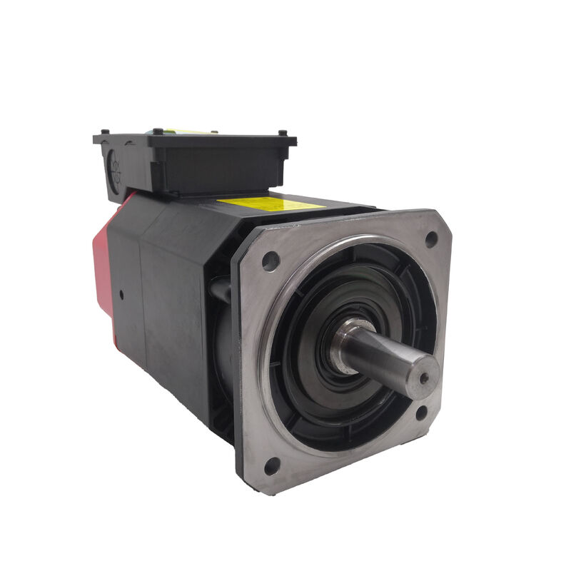
Fanuc A06B-1404-B100 | Alpha i Series AC Spindle Motor AII 2/10000 — 2.2–3.7kW, Flange Mount, IM, Rear Exhaust
Part Number: A06B-1404-B100
Type: AC Spindle Motor
Series: Alpha i (αi)
Model: AII 2 / 10000
Configuration: Flange Mount, Inner Motor (IM), Rear Exhaust Cooling
Speed Range: 1,500–10,000 RPM
Condition: New / Refurbished / Surplus
Overview
The Fanuc A06B-1404-B100 is an AC spindle motor from Fanuc's Alpha i series — model AII2/10000 — configured as a flange-mounted inner motor with rear exhaust cooling. With a continuous rated output of 2.2 kW rising to 3.7 kW in short-duration and intermittent duty cycles, and an operating speed range that runs from 1,500 to 10,000 RPM, this is a compact, high-speed spindle motor built for the demands of CNC turning centres, compact machining centres, and multi-function CNC platforms where spindle performance directly determines cutting productivity and part quality.
The inner motor configuration — identified by the IM designation — distinguishes this variant from the standard slick-shaft version of the same motor. Rather than driving the spindle through a belt, coupling, or gear arrangement, the IM motor integrates directly into the machine's spindle assembly.
The rotor is mounted directly onto the spindle shaft, and the stator is built into the spindle head housing. This arrangement eliminates the transmission components between motor and spindle, removing their associated backlash, vibration contribution, and mechanical losses from the drive train entirely.
The AII2/10000 serves on the lower end of the Alpha i spindle power range, where compact machine platforms require a spindle motor that fits within tight dimensional constraints without sacrificing the speed ceiling that high-productivity machining demands.
At 10,000 RPM, the motor supports the high-speed cutting strategies that reduce cycle times on aluminium, light alloys, and non-ferrous materials, while the 3-phase 110–220VAC input compatibility makes it suitable for both 200V and dual-voltage drive configurations.
Key Specifications
| Parameter |
Value |
| Rated Output (S1 Continuous) |
2.2 kW |
| Rated Output (S2 / S3 Duty) |
3.7 kW |
| Speed Range |
1,500 – 10,000 RPM |
| Input Voltage |
110–220 VAC |
| Phase |
3-Phase |
| Poles |
4 |
| Mounting |
Flange |
| Configuration |
Inner Motor (IM) |
| Cooling |
Rear Exhaust |
| Series |
Alpha i — AII2/10000 |
S1, S2, and S3 Duty Ratings — Reading the Power Specification
The three power ratings on the AII2/10000 describe three different operating conditions, not three different motors. Understanding which applies to a given application determines whether the motor is correctly sized.
S1 (2.2 kW) is continuous duty — the motor can sustain this output indefinitely without exceeding its thermal limits.
This is the figure to use when the spindle is running at rated power for extended periods, as in facing operations, threading passes, or sustained contouring cuts.
S2 and S3 (3.7 kW) represent intermittent duty ratings — S2 covering defined short-duration bursts and S3 covering cyclic operation at a defined on/off ratio. In milling, drilling, and turning cycles that involve alternating heavy cuts and light finishing passes or tool changes, the spindle can draw on the 3.7 kW rating for the heavy phases without sustained thermal build-up.
For machine tool applications, the S3 rating is often the more operationally relevant figure, since most production machining involves cyclic loading rather than constant heavy cutting.
The AII2/10000's ability to deliver 3.7 kW on a duty cycle basis provides effective cutting power that exceeds what the nameplate S1 rating alone suggests.
Inner Motor Configuration — Why IM Changes Everything
In a conventional belt-drive or direct-couple spindle arrangement, the motor sits alongside or behind the spindle head, connected through a transmission.
The IM motor integrates the electromagnetic assembly directly into the spindle: the stator is housed inside the spindle head casting, and the rotor is mounted on the spindle shaft itself. There is no transmission — the motor and spindle are mechanically one assembly.
The consequences of this integration flow in several directions. Rotational accuracy improves because the path from commanded torque to spindle response has no compliance, no gear mesh, and no belt stretch to absorb. Spindle speed response is faster for the same reason.
Vibration characteristics improve because there are fewer rotating masses in the system and no transmission-induced excitation frequencies. Above 5,000 RPM, the advantages of eliminating belt whip and coupling imbalance become increasingly significant for surface finish quality.
The installation context also changes. An IM motor is not a standalone unit installed in a motor bay — it is assembled into the spindle head as part of the spindle build, with the rotor pressed or fitted to the spindle shaft and the stator fitted to the housing bore. When servicing an IM motor, the spindle head is typically disassembled to access the motor components.
This places demands on the service capability of whoever handles the repair: spindle bearing preload, shaft runout, and component alignment all become part of the motor refurbishment scope.
Speed Range and the 1,500–10,000 RPM Operating Envelope
The 1,500 RPM lower bound of the AII2/10000's speed range is not an absolute minimum speed — it is the speed below which the motor is rated for constant torque operation rather than constant power. Below 1,500 RPM, torque remains at its rated value but power output decreases in proportion to speed.
This region is used for low-speed turning operations, tapping, and rigid tapping cycles where torque rather than power is the governing parameter.
From 1,500 RPM to 10,000 RPM, the motor operates in its constant-power zone — the spindle amplifier provides field weakening as speed increases above the base speed, maintaining rated power output across the full speed range.
At 10,000 RPM the motor reaches its maximum operating speed, which supports the surface speed requirements of high-speed machining strategies on aluminium, brass, and other non-ferrous workpiece materials with small-diameter tooling.
The MZi sensor fitted to this motor family provides the speed and position feedback the spindle amplifier uses to regulate speed and support oriented stop and Cs axis (contour axis) functions.
Oriented stop is the function that locks the spindle at a defined angular position for tool changes and workpiece loading; Cs axis converts the spindle into a controlled positioning axis for milling interpolation and complex turn-mill cycles on multi-function platforms.
Rear Exhaust Cooling
The rear exhaust cooling configuration draws air through the motor body and exhausts it from the rear — away from the spindle nose end and the working zone. In a flange-mounted inner motor installation, the motor sits within the spindle head casting, and cooling air routing is part of the spindle head design.
Rear exhaust directs the motor's generated heat away from the spindle bearing zone and out of the machine through rear-facing ducting, preventing thermal gradients across the spindle assembly that could affect bearing preload and dimensional stability during extended cutting operations.
For spindle accuracy, thermal stability matters as much as the motor's speed and torque characteristics.
A motor that exhausts heat toward the spindle bearings will cause differential thermal expansion that shifts the spindle centerline during warmup — a problem that becomes visible as dimensional drift on workpieces measured cold versus warm. Rear exhaust addresses this systematically at the design level.
Drive & Amplifier Compatibility
The A06B-1404-B100 is designed for use with Fanuc's Alpha i series spindle amplifiers. The earlier 6141 and 6142 series amplifiers, and the later 6220 series, are compatible with the AII2/10000 motor family.
The motor integrates with Fanuc CNC platforms including Series 0i-C, 0i-D, and 30i/31i/32i (3xi series).
The spindle amplifier must be parameterised with the correct motor type code for the AII2/10000 before the spindle is operated, and the MZi sensor cable must be correctly routed and connected for speed feedback and oriented stop functions to operate.
FAQ
Q1: What is the difference between the A06B-1404-B100 (IM) and the A06B-1404-B103 (SLK) variants?
Both are AII2/10000 Alpha i spindle motors sharing the same electrical specification — 2.2kW S1 / 3.7kW S2-S3, 1,500–10,000 RPM, 110–220VAC. The B100 is the inner motor (IM) variant: no protruding shaft, designed for direct integration into a spindle head assembly where the rotor mounts onto the machine's own spindle shaft.
The B103 is the slick shaft (SLK) variant: it has a plain output shaft for belt-drive or direct-couple arrangements to a separate spindle. The two variants require fundamentally different machine designs and are not interchangeable without substantial mechanical modification.
Q2: What does the S1 / S2 / S3 power rating mean for daily machining use?
S1 (2.2 kW) is the continuous rating — sustained cutting at this power level indefinitely. S2 and S3 (3.7 kW) are intermittent ratings used during duty cycles that include lower-power phases between heavy cuts.
Most production CNC machining involves cyclic loading, so the motor effectively delivers 3.7 kW during the cutting phases of typical operational cycles. Exceeding the continuous S1 rating for sustained periods beyond the S2/S3 time definitions will push the motor into thermal overload, which the amplifier monitors and protects against.
Q3: Which Fanuc spindle amplifier is compatible with the A06B-1404-B100?
The AII2/10000 is compatible with Fanuc Alpha i spindle amplifiers including the 6141/6142 series and the later 6220 series. It integrates with Fanuc CNC controls including Series 0i-C, 0i-D, and 3xi (30i/31i/32i).
The amplifier must carry the correct spindle motor type parameter for the AII2/10000 before the spindle is run. The MZi sensor cable must also be correctly connected and the sensor interface enabled in the drive parameters for oriented stop and spindle speed feedback to function.
Q4: What service is required when an IM spindle motor fails on a CNC machine?
Unlike a belt-drive motor that can be unbolted and replaced in the field, an inner motor repair requires spindle head disassembly. The stator is housed in the spindle head bore and the rotor is mounted on the spindle shaft — both require extraction with appropriate fixtures to avoid shaft and bearing damage.
Spindle bearing replacement is typically performed at the same time since the assembly is opened.
This is specialist work: spindle runout, bearing preload, and shaft alignment must all be re-established to original specification before the spindle is returned to service. Specialist spindle repair facilities with appropriate fixturing and test equipment are the correct service route for IM motors.
Q5: What are the most important checks when evaluating a used A06B-1404-B100?
For a dismounted IM motor assembly, check the rotor surface for scoring, corrosion, or eccentricity visible on inspection.
Measure winding resistance between phases for balance and verify insulation resistance to earth — both phases and earth measurement are important for a motor that may have seen coolant contamination inside the spindle head. Inspect the MZi sensor and its cable exit for damage.
Check that the rotor rotates freely within the stator bore with consistent radial clearance on rotation.
A bench test running the motor at incremental speeds up to rated maximum with spindle amplifier current monitoring is the correct pre-installation verification before the motor is built back into a spindle head for production service.

 Your message must be between 20-3,000 characters!