Fanuc A06B-1444-B200 | Beta ii Series AC Spindle Motor Bii 3/10000 — 3.7/5.5kW, Foot Mount, Slick Shaft, Rear Exhaust
Part Number: A06B-1444-B200
Type: AC Spindle Motor
Series: Beta ii (βii)
Model: Bii 3 / 10000
Configuration: Foot Mount, Slick Shaft (No Keyway), Rear Exhaust Cooling
Speed Range: 1,500 – 10,000 RPM
Condition: New / Refurbished / Surplus
Overview
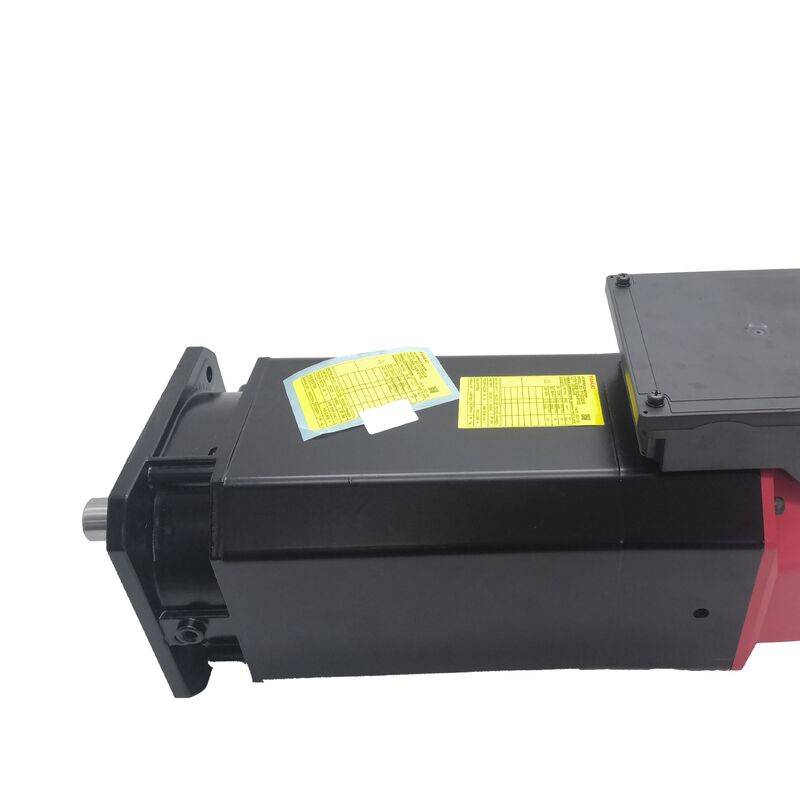
The Fanuc A06B-1444-B200 is a Beta ii series AC spindle motor — model Bii 3/10000 — configured with foot mounting, a plain slick shaft, and rear exhaust cooling.
Rated at 3.7 kW continuous and 5.5 kW in short-duty and intermittent operation, with a 10,000 RPM maximum speed, this is a compact, cost-effective spindle motor from Fanuc's economy-tier spindle line, designed for the smaller CNC machining centres, drill-tap centres, and entry-level turning centres where the Beta ii architecture delivers the spindle functions needed for productive machining without the higher current and amplifier demands of the Alpha i series.
The foot mount is what makes the B200 variant distinctive within the Bii 3/10000 family.
Where the B103 and B203 variants carry flange mounting for integration into the machine's spindle head casting, the B200 uses a foot — a base-mounted configuration that attaches the motor at its underside rather than at its front face.
This mounting approach is used in machine tool spindle architectures where the motor sits behind and below the spindle assembly, driving it through a belt or coupling arrangement, rather than being integrated directly into the spindle head.
At 10,000 RPM, the Bii 3/10000 covers the speed range needed for productive cutting on aluminium, non-ferrous alloys, and smaller-diameter carbide tooling.
The 5.5 kW peak output is adequate for the duty cycles typical of the machine class this motor serves, and the Beta ii platform's compatibility with the cost-effective βiSVSP amplifier module makes the complete spindle drive system appropriate for entry-level CNC machine tool configurations.
Key Specifications
| Parameter |
Value |
| Rated Output (S1 Continuous) |
3.7 kW |
| Rated Output (S2 / S3 Duty) |
5.5 kW |
| Speed Range |
1,500 – 10,000 RPM |
| Mounting |
Foot |
| Shaft Type |
Slick (Plain, No Keyway) |
| Cooling |
Rear Exhaust |
| Phase |
3-Phase |
| Series |
Beta ii (βii) — Bii3/10000 |
Beta ii Series — Cost-Effective CNC Spindle Architecture
The Beta ii spindle motor series occupies Fanuc's economy-tier spindle position, designed for machine tool builders who need reliable CNC spindle capability at a lower drive system cost than the Alpha i series requires.
The Beta ii integrates with the βiSVSP combined servo-spindle amplifier — an all-in-one module that handles both servo axis and spindle functions from a single unit, reducing drive cabinet volume and overall system cost for the compact CNC platforms this motor series serves.
At 3.7 kW S1 and 5.5 kW S2/S3, the Bii 3/10000 is correctly sized for the spindle power demands of small machining centres with spindle tapers up to BT30 or HSK-A40, drill-tap centres running short-cycle operations, and compact lathes where the spindle motor size is constrained by the machine's mechanical envelope.
The spindle drives aluminium profiling, light steel drilling, and non-ferrous alloy milling efficiently within these power ratings, and the 10,000 RPM ceiling provides adequate surface speed for small carbide tooling across a wide range of workpiece materials.
The distinction between S1 and S3 duty ratings matters in production use. The 3.7 kW S1 is the output the motor sustains indefinitely — appropriate for extended facing passes or sustained turning operations.
The 5.5 kW S3 applies during duty cycles that include lower-power recovery phases between heavy cuts, which describes most practical milling and drilling cycles. For spindle drive selection and cabinet sizing, the S3 figure governs the amplifier's thermal management requirements.
Foot Mount — What It Means for Installation
The B200 variant's foot mount is the single feature that most directly determines its installation context.
A foot-mounted motor attaches through the motor's base, sitting on or bolted to a mounting surface within the machine's drive compartment. The motor's output shaft extends forward toward the driven mechanism — a belt pulley, a coupling hub, or a gear input — rather than the motor face bolting directly to the spindle casting.
This arrangement is used in spindle drive designs where the motor position, orientation, or the required transmission ratio between motor and spindle makes a belt or coupling drive preferable to direct flange integration.
Foot mounting provides more flexibility in motor placement relative to the spindle axis — the motor can be positioned offset, parallel, or at a specific distance to suit belt tension requirements or available space — while maintaining the ability to achieve any required speed ratio through pulley selection.
The contrast with the flange-mounted B103 variant of the same Bii 3/10000 is direct: the B103 bolts face-on to the spindle head or support structure; the B200 bolts base-down to a shelf or mounting surface.
The mounting bolt pattern and overall motor geometry differ between the two variants in ways that make them non-interchangeable without mechanical modification to the machine.
Slick Shaft at 10,000 RPM — Balance and Coupling
The slick shaft on the A06B-1444-B200 presents a clean, symmetric cylindrical surface without a keyway. At 10,000 RPM maximum speed, the rotational balance of the shaft and its drive element — belt pulley, coupling hub, or sprocket — influences spindle vibration at the upper end of the speed range.
A keyway slot introduces an asymmetric geometric discontinuity that adds a small imbalance contribution; the slick shaft eliminates this.
On a motor this size and at these speeds, the practical effect on vibration amplitude is real, particularly in the constant-power zone from base speed to 10,000 RPM.
Torque transmission from the slick shaft to the driven component relies entirely on the friction generated by the coupling hub's clamping force.
For the 5.5 kW peak output and the torque levels the Bii 3/10000 generates at this speed, a correctly specified coupling component clamped to the manufacturer's specified torque value handles the load reliably. The installation responsibility is applying — and verifying — that clamping torque correctly.
Under-torqued clamping allows progressive slip that manifests as shaft fretting, increasing runout, and eventually axis positioning error before the root cause is identified.
Rear Exhaust — Heat Away from the Spindle Zone
The rear exhaust configuration draws cooling air through the motor body and expels it from the rear face. For a foot-mounted motor, this means the motor's generated heat exits toward the back of the machine's drive compartment rather than toward the spindle.
The cooling airflow path should be clear of obstructions, and the machine-side ductwork or enclosure must be designed to allow the exhaust air to dissipate rather than recirculate back through the motor intake.
At 5.5 kW peak output in a compact motor frame, heat management matters to sustained performance.
A blocked or restricted exhaust path raises motor temperature under sustained duty cycles, which the amplifier's thermal protection monitors and responds to by reducing available output current. The practical symptom is spindle derating at inopportune moments during heavy cutting.
Confirming that the exhaust path is unobstructed is part of both initial installation commissioning and periodic maintenance inspection.
Spindle Functions and Amplifier Compatibility
The Bii 3/10000 is designed for the Fanuc βiSVSP combined servo-spindle amplifier, and integrates with Fanuc CNC controls including Series 0i-D, 0i-F, and other Fanuc CNC platforms that support the Beta ii spindle architecture.
The amplifier must carry the correct motor type parameter for the Bii 3/10000 before the spindle is operated. The motor also supports oriented stop and rigid tapping functions through its spindle sensor interface — confirming that the sensor interface is enabled in the amplifier parameters is a required commissioning step.
FAQ
Q1: What is the difference between the A06B-1444-B200 (foot mount) and the A06B-1444-B103 (flange mount)?
Both are Bii 3/10000 Beta ii spindle motors sharing the same 3.7/5.5 kW output, 1,500–10,000 RPM speed range, slick shaft, and rear exhaust configuration. The B200 has a foot mount — the motor attaches through its base to a mounting surface.
The B103 has a flange mount — the motor bolts face-on to the spindle head or support casting. The mounting geometry, bolt pattern, and installation layout differ between the two in ways that make them non-interchangeable without mechanical modification to the machine.
Confirm the mounting type on the installed motor before ordering a replacement.
Q2: What spindle amplifier is compatible with the A06B-1444-B200?
The Bii 3/10000 is designed for the Fanuc βiSVSP combined servo-spindle amplifier module. This integrated drive module handles both servo feed axis and spindle functions from a single unit, which is characteristic of the Beta ii architecture in compact CNC machine tool configurations.
The amplifier motor type parameter must be set for the Bii 3/10000 and the spindle sensor interface enabled before the spindle is operated.
The βiSVSP must also be appropriately sized for the 5.5 kW peak spindle power requirement.
Q3: What is the difference between the 3.7 kW and 5.5 kW power ratings?
The 3.7 kW is the S1 continuous rating — the output the motor can sustain indefinitely. The 5.5 kW is the S2/S3 intermittent rating — available during the high-demand phases of a cutting cycle that also includes lower-power recovery phases.
Most CNC machining cycles are intermittent in nature, so the motor effectively delivers 5.5 kW during the heavy cutting phases. Sustained operation at 5.5 kW beyond the S2/S3 duty cycle definition will cause thermal overload, which the amplifier's protection circuits detect and manage.
Q4: Does the slick shaft create any torque transmission risk at this power level?
No, provided the coupling component is correctly specified and installed. The slick shaft relies entirely on friction — generated by the coupling hub's clamping force — to transmit torque. At the Bii 3/10000's output level, a correctly rated and properly clamped coupling handles the torque without risk of slip.
The critical requirement is verifying the hub clamping torque against the coupling manufacturer's specification at installation and during periodic service checks. An under-torqued coupling is the most common cause of shaft fretting and progressive shaft runout on plain-shaft spindle motors.
Q5: What are the most important inspection steps for a used A06B-1444-B200?
Inspect the slick shaft surface for fretting marks from previous coupling damage or improper installation — fretting on the shaft surface indicates coupling slip and requires assessing whether the shaft diameter tolerance has been compromised.
Check the cooling fan and rear exhaust path for obstructions, debris, or fan blade damage. Measure winding resistance across all three phases for balance and verify insulation resistance to earth. Inspect the sensor interface and its cable connector for damage.
Rotate the shaft by hand to assess bearing condition. A bench run-up to 10,000 RPM on a compatible βiSVSP amplifier with current monitoring is the correct final check before the motor is commissioned on a production machine.

 Your message must be between 20-3,000 characters!