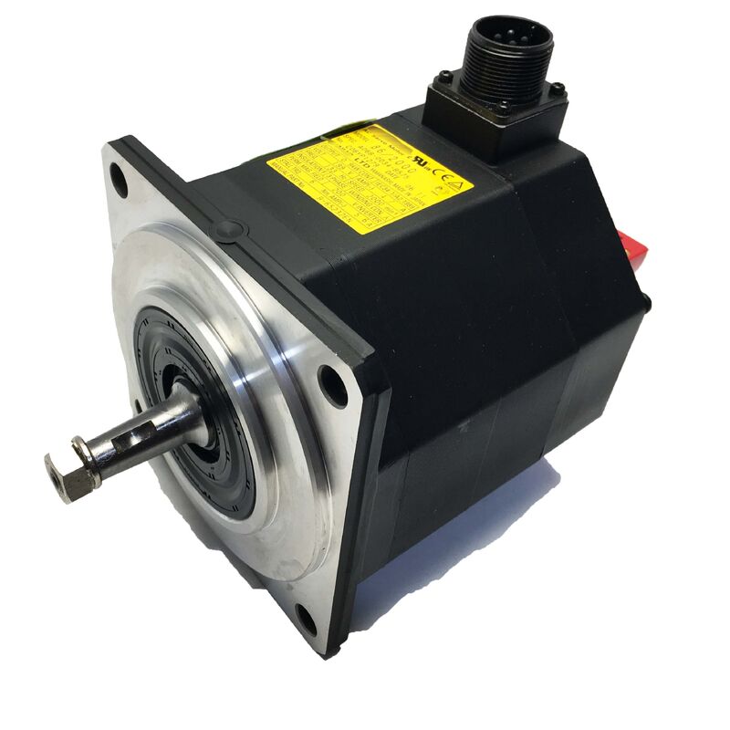
Fanuc A06B-0087-B403 | Beta iS AC Servo Motor BiS30/2000 — 3kW, 27Nm, Straight Shaft, 24V Brake, biA128 Encoder
Part Number: A06B-0087-B403
Series: Beta iS (βiS) AC Servo Motor
Model: BiS 30 / 2000
Configuration: Straight Plain Shaft (SLK), 24V DC Spring-Applied Brake, biA128 Absolute Encoder, IP65
Rated Output: 3 kW
Stall Torque: 27 Nm
Maximum Speed: 2,000 RPM
Input Voltage: 200–240 VAC, 3-Phase
Brake Supply: 24V DC
Weight: 29 kg
Encoder: biA128 Absolute (A860-2020-T301)
Condition: New / Refurbished
Overview
The Fanuc A06B-0087-B403 is the brake-equipped variant of the BiS30/2000 — a 3 kW, 27 Nm Beta iS series AC servo motor configured with a straight plain shaft, 24V DC spring-applied brake, biA128 absolute pulsecoder, and IP65 sealing.
The "403" suffix is the suffix pattern across Fanuc's Beta iS family for straight plain shaft, brake, biA128 encoder — the same suffix logic used on the BiS8/3000-B403, the BiS22/2000-B403, and others.
At 29 kg, this is a substantial motor: the largest of the Beta iS compact range before the BiS40/2000 above it, and the correct specification for axes that need both high holding torque and a mechanical safety brake.
The brake is what this motor is for, beyond just the BiS30/2000 performance.
The B103 variant delivers the same 27 Nm stall torque, the same absolute encoder, the same IP65 protection — but it carries no brake. When an axis can move under gravity, spring pressure, or stored elastic energy whenever servo torque is removed, the B103 is not the right motor regardless of how well matched its torque is to the load.
The A06B-0087-B403 exists specifically for those axes: the vertical Z-axes of vertical machining centres, the tilting axes of five-axis machine platforms, the rotary axes of large positioners and indexers, and any automation axis where servo-off means uncontrolled mechanical movement unless a brake is present.
Key Specifications
| Parameter |
Value |
| Rated Output |
3 kW |
| Stall Torque |
27 Nm |
| Maximum Speed |
2,000 RPM |
| Input Voltage |
200–240 VAC |
| Phase |
3-Phase |
| Brake Supply Voltage |
24V DC |
| Brake Type |
Spring-Applied, Electrically Released |
| Encoder |
biA128 Absolute (A860-2020-T301) |
| Encoder Resolution |
128,000 ppr |
| Shaft Type |
Straight Plain (SLK, No Keyway) |
| Ingress Protection |
IP65 |
| Weight |
29 kg |
| Series |
Beta iS (βiS) — BiS30/2000 |
The 24V DC Brake — Why It Exists and How It Works
The brake fitted to the A06B-0087-B403 is spring-applied and electrically released — the default state is engaged, and the brake requires an active 24V DC supply to open.
When power is present and the servo is running normally, the 24V DC brake supply energises the brake coil, the electromagnet overcomes the spring force, and the brake disc separates from the friction surface. The shaft turns freely.
When the 24V supply is removed — whether by deliberate servo-off command, E-stop, or power interruption — the spring immediately drives the brake surfaces together and holds the shaft mechanically.
This fail-safe logic is the reason the brake exists. No control logic can provide equivalent mechanical security.
If the servo amplifier faults, if the control power supply fails, if the machine loses mains supply, or if the emergency stop circuit trips — in all of these cases the brake engages without any active signal from the CNC or the PLC.
The axis holds position mechanically, regardless of what is happening in the electrical system.
At 27 Nm motor stall torque, the brake's holding torque is designed to match the motor's load class.
The specific holding torque of the A06B-0087-B403 brake is sized for the BiS30/2000 application range — sufficient to hold the axis load statically when the motor is not energised, against gravity, spring preload, or residual pneumatic force depending on the machine's axis configuration.
The brake is not intended for use as a dynamic stop while the motor is running under full torque — it is a parking brake, not a friction stop for deceleration.
The 24V DC specification must be correct. The Beta iS series brakes use 24V DC, not the 90V DC found on Fanuc's larger Alpha series motors. Applying 90V to a 24V coil will immediately burn the brake winding.
Applying only 24V to a 90V coil will produce partial electromagnetic release — the spring is never fully overcome, the brake drags against the disc during motor operation, and both the brake and the motor suffer progressive thermal and mechanical damage.
Before commissioning a replacement motor, measure the machine's brake supply voltage at the brake connector terminals to confirm 24V DC.
BiS30/2000 Performance — Where 27 Nm Matters
The 27 Nm stall torque of the BiS30/2000 is the defining parameter for the axis types this motor serves. Stall torque is the maximum torque available from the motor at standstill — the torque the servo amplifier delivers to hold a commanded position against an applied load.
For a vertical Z-axis carrying a heavy spindle head, the stall torque requirement includes the weight of the head, the friction of the linear guideway carriage seals, and any cutting force components transmitted back through the spindle.
For a tilting table, it includes the combined moment of the table mass, workpiece, and fixture acting about the tilt axis pivot.
At 2,000 RPM maximum speed, the BiS30/2000 is not a high-speed motor.
The tradeoff inherent in the Beta iS design is that higher stall torque at compact frame size comes at the cost of maximum operating speed. The BiS30/2000's working range is optimised for 0–2,000 RPM — the speed range typical of the driven axes it serves.
Rapid traverse rates on heavy vertical axes are limited more by the axis's acceleration capacity (which depends on available torque minus load torque) than by motor speed, and 2,000 RPM at the typical ball screw pitch and gear ratio for heavy-axis applications is usually adequate.
Straight Plain Shaft with 27 Nm — Coupling Requirements
The plain slick shaft transmits the full 27 Nm stall torque to the driven component by friction alone — the coupling hub clamps the shaft and holds through contact pressure at the bore surface.
With a brake added to the assembly, there is an additional consideration: when the brake engages and holds the axis stationary while an external force is trying to move it — during an E-stop while machining, for example — the coupling interface may experience impact torque loading that exceeds the static torque capacity the friction clamping was sized for.
This is worth addressing at the coupling specification stage.
The hub clamping force must be sized for the brake's holding torque, not just the motor's running torque, and must account for dynamic loading during brake engagement.
A coupling hub that is adequate for 27 Nm running torque but under-specified for the mechanical shock of brake engagement against a moving load will progressively fret, and the fretting will manifest as shaft runout and position repeatability degradation before the coupling fails completely.
In practice this means: confirm the coupling manufacturer's dynamic torque rating, not just the static torque rating, when specifying the coupling for a braked motor installation.
biA128 Absolute Encoder — Position Without Homing
The biA128 pulsecoder (A860-2020-T301) retains full shaft position reference through power cycles without any backup battery. When the servo system powers up — whether after a planned shutdown or after an unplanned power loss event — the CNC reads the true shaft position directly from the biA128. No reference return, no homing traverse, no startup delay for position establishment.
On a vertical axis or tilting axis with a mechanical brake, this combination is particularly practical. The axis does not move during power-off because the brake holds it. When power is restored, the biA128 reads the shaft position — still at the same angle it was when power was removed — and the CNC immediately has correct position data.
The machine can resume production from exactly where it stopped without any repositioning cycle. On incremental encoder systems, a homing reference return would be required before any axis command could be accepted, adding startup time proportional to the axis length and reference return speed.
IP65 and Beta i Amplifier Compatibility
IP65 sealing protects the A06B-0087-B403 against the coolant mist and incidental water jet exposure typical of a production machining environment. At 29 kg, this motor is large enough that the shaft seal — part of the IP65 assembly — carries meaningful radial load from the coupling and any belt tension if the axis uses a belt drive.
The shaft seal condition should be included in periodic maintenance checks alongside bearing condition.
The motor is designed for Fanuc's Beta i servo amplifier family — βiSV single-axis drives and the βiSVSP combined servo-spindle module — sized for the BiS30/2000's 3 kW output class. It integrates with Fanuc CNC controls including Series 0i-C, 0i-D, 0i-F, 30i, 31i, and 32i.
The 24V DC brake supply is a separate circuit from the servo amplifier output — it must be independently powered from the machine's 24V DC control supply and correctly interlocked so the brake releases before servo enable and engages before servo disable.
An incorrectly interlocked brake circuit — one that releases too late or engages too early relative to the servo enable/disable timing — produces either servo overload alarms (motor fighting the brake during startup) or uncontrolled position drift (brake releasing while the servo is still disabled).
FAQ
Q1: What is the difference between the A06B-0087-B403 and the A06B-0087-B103?
Both are BiS30/2000 motors sharing the same 3 kW rated output, 27 Nm stall torque, 2,000 RPM maximum speed, straight plain shaft, biA128 absolute encoder, and IP65 construction. The single difference is the brake: the B403 carries a 24V DC spring-applied brake; the B103 does not. The B403 is specified for axes where servo torque removal allows uncontrolled gravitational, spring, or load-driven movement — vertical axes, tilting axes, and load-bearing rotary axes. The B103 is correct for horizontal and balanced axes where this risk is absent. Installing a B103 on an axis that requires a brake creates a safety hazard.
Q2: The brake supply is 24V DC. Why is this voltage critical?
The BiS30/2000 brake coil is designed for 24V DC. Fanuc's larger Alpha series motors use 90V DC brakes. Applying 90V to this motor's 24V brake coil burns the winding immediately.
Applying 24V to a 90V coil produces partial electromagnetic release — the spring is not overcome, the brake drags against the friction disc during running, generating heat and causing progressive mechanical damage to both brake and motor bearings.
Before connecting power, measure the machine's brake supply voltage at the brake cable connector and confirm 24V DC.
Q3: Can the brake be used as a dynamic stop while the motor is turning?
No. The spring-applied brake on the A06B-0087-B403 is a holding brake (parking brake), not a dynamic friction brake. It is designed to hold the axis stationary when servo torque is removed — at standstill, or during deceleration to zero.
Engaging the brake against a rotating motor at significant speed generates friction heat that exceeds the brake's thermal design, degrades the brake pad material rapidly, and can damage the motor shaft bearing due to the radial load created by brake disc deflection under impact.
Dynamic stopping is the servo amplifier's responsibility, through controlled current deceleration.
Q4: After an E-stop with power loss, does the axis need to be re-homed before production can resume?
No. The biA128 absolute encoder retains shaft position through power interruptions — when the servo system restores power, the CNC reads the true shaft angle directly from the encoder.
Because the mechanical brake holds the axis stationary during the power-off interval, the shaft has not moved.
The CNC has accurate position data immediately after power restoration, and the machine can resume from exactly the position it was in when the E-stop occurred, without any reference return or homing traversal.
Q5: What are the most important inspection checks for a used A06B-0087-B403?
Test the brake first — apply 24V DC and confirm the shaft spins freely without drag; remove 24V and confirm the shaft locks solidly without creep under manual torque. A brake that partially releases or fails to hold completely requires service before the motor goes on any axis. Inspect the plain shaft surface for fretting from a previously slipped coupling hub.
At 27 Nm, fretting on the shaft surface is more significant than on lighter Beta iS motors — assess whether the shaft surface is within dimensional tolerance before fitting a new coupling.
Check the biA128 encoder connector (A860-2020-T301) for corroded pins, and the cable exit strain relief for cracking. Measure winding resistance across all three phases and check insulation resistance to earth.
A bench run-up to 2,000 RPM on a Beta i amplifier with the brake correctly interlocked, absolute encoder position verified, and load current monitored is the correct final check before the motor is installed on the machine.

 Your message must be between 20-3,000 characters!