Fanuc A06B-0127-B177 | Alpha Series AC Servo Motor α6/2000 — 1.0kW, 6Nm, Taper Shaft, 90V Brake, A1000 Encoder
Part Number: A06B-0127-B177
Series: Alpha (α) AC Servo Motor
Model: α6 / 2000
Configuration: Tapered Shaft with Keyway, 90V DC Spring-Applied Brake, A1000 Absolute Encoder, IP65
Rated Output: 1.0 kW
Stall Torque: 6 Nm
Rated Speed: 2,000 RPM
Motor Voltage: 140 VAC
Rated Current: 4.6 A
Rated Frequency: 133 Hz
Phase: 3-Phase
Condition: New / Refurbished
Overview
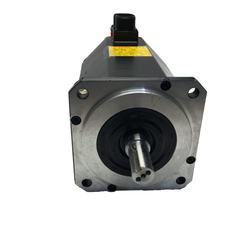
The Fanuc A06B-0127-B177 is an Alpha series AC servo motor — model α6/2000 — configured with a tapered shaft, 90V DC spring-applied brake, and A1000 absolute encoder. Rated at 1.0 kW, 6 Nm stall torque, 140V, 4.6A, and 133 Hz operating frequency at 2,000 RPM, this motor covers the moderate-torque feed axis applications that the Alpha generation machine tools were built around: a direct replacement or upgrade path for older Fanuc servo motor generations running the same α6/2000 electrical platform, with the A1000 encoder's high-resolution absolute feedback providing a meaningful step up in positioning accuracy and startup behaviour over the I64 incremental encoder found in earlier variants of the same motor.
Three configuration elements make the B177 what it is within the A06B-0127 product family. The taper shaft provides self-centering concentric positioning between the motor and its driven component — a pulley, coupling hub, or gear — and the mechanical interference fit that develops under torque loading eliminates the micro-movement at the motor-load interface that can develop over time on straight-shaft plain clamping arrangements under sustained vibration.
The 90V DC brake provides fail-safe holding whenever the servo amplifier is disabled.
The A1000 encoder returns 1,000,000 pulses per revolution to the servo drive, supplying absolute position data without the need for reference return after any power interruption.
Key Specifications
| Parameter |
Value |
| Rated Output |
1.0 kW |
| Stall Torque |
6 Nm |
| Rated Speed |
2,000 RPM |
| Motor Voltage |
140 VAC |
| Rated Current |
4.6 A |
| Rated Frequency |
133 Hz |
| Phase |
3-Phase |
| Shaft Type |
Tapered with Keyway |
| Brake |
90V DC Spring-Applied |
| Encoder |
A1000 Absolute (1,000,000 ppr) |
| Ingress Protection |
IP65 |
| Series |
Fanuc Alpha — α6/2000 |
α6/2000 in the Alpha Servo Lineup
The α6/2000 motor sits in the lower-middle range of the Alpha series servo motor family — rated at 1.0 kW continuous and 6 Nm stall torque, running to 2,000 RPM.
In the context of CNC machine tools from the Alpha generation, this motor class typically served the lighter axes of small to medium machining centres: the fourth rotary axis, the B-axis tilt on some platforms, secondary positioning axes, and on compact machines, primary X/Y/Z axes where table and workpiece mass kept axis load within the motor's comfortable operating range.
The "6" in α6/2000 refers to the stall torque class in the Fanuc Alpha naming convention, and the "/2000" defines the maximum speed.
This places the α6/2000 below the α6/3000 (same torque, higher speed) and α12/2000 (higher torque, same speed) in the Alpha family progression.
Choosing the correct motor in this range requires matching the axis load inertia and peak torque demand against what the motor can deliver at the required acceleration rate — the 6 Nm stall torque defines what the motor can hold at zero speed, while the continuous torque-speed curve determines what it can sustain through a full machining cycle.
Tapered Shaft — Self-Centering Mechanical Interface
The tapered shaft on the A06B-0127-B177 is a self-centering interference-fit shaft design. As the mating component — pulley, sprocket, coupling hub, or timing belt pulley — is drawn onto the taper by its retention nut or bolt, the increasing diameter of the taper generates an increasing interference between shaft and bore.
When correctly installed to the specified torque, this interference fit creates a friction contact area distributed across the full taper length, rather than the concentrated point contact of a straight keyway interface.
The taper also solves the alignment problem inherent in straight-shaft motor installation.
A tapered bore hub seats concentrically on the taper by geometry — its only equilibrium position on the shaft is the one where the taper diameters match.
There is no possibility of eccentric seating if the hub bore is correctly sized, which means the rotating assembly is inherently balanced without additional shimming or alignment adjustment.
The keyway on the taper shaft adds positive rotational engagement to the interference fit's axial and radial retention.
The key prevents relative rotation between shaft and hub should the interference fit be partially overcome under extreme shock loading or vibration — a situation more common on Alpha series motors driving ball screws through toothed belt drives than on direct-coupled arrangements, where belt tension imposes a sustained radial load on the shaft.
Taper shaft removal requires a proper puller — a device that pushes the hub off the taper axially by forcing against the shaft end face while pulling on the hub flange.
Attempting to remove a correctly installed taper shaft component by hammering or prying risks shaft damage, hub damage, and encoder damage from the shock transmitted through the motor body.
90V DC Brake — Alpha Series Fail-Safe Holding
The brake fitted to the A06B-0127-B177 is spring-applied and released by 90V DC. This is the standard Alpha series brake voltage — different from the 24V DC brakes used on the Beta iS and Beta i series motors.
The spring pre-loads the brake disc against the friction surface at all times; applying 90V DC energises the coil, overcomes the spring force, and holds the brake disc clear of the friction surface while the motor runs.
Remove the 90V supply — by servo disable, E-stop, or power loss — and the spring immediately engages the brake.
The 90V specification is not negotiable. Applying 24V to a 90V brake coil generates insufficient electromagnetic force to overcome the spring, leaving the brake partially engaged. The motor runs against continuous brake drag: the brake pad surface heats up, the bearing takes abnormal radial load from the deflected disc, and both components deteriorate progressively.
The error presents initially as higher-than-normal servo current draw and elevated motor temperature, without an immediate alarm — the damage accumulates silently until either the brake or the motor fails.
Before connecting power to any replacement A06B-0127-B177, confirm the machine's brake supply voltage at the brake cable connector with a DC voltmeter.
Machines using the Alpha servo generation are designed around 90V DC brake supplies; confusion arises only when motors from different generations are mixed in the same panel.
A1000 Absolute Encoder — One Million Pulses Per Revolution
The A1000 pulsecoder on the A06B-0127-B177 returns absolute position data at 1,000,000 pulses per revolution.
The resolution this represents at the machine axis depends on the motor-to-axis transmission ratio — on a typical 10mm-pitch ball screw with a 1:1 motor coupling, 1,000,000 ppr at the motor translates to 0.01 μm per pulse resolution at the table, which is orders of magnitude finer than the mechanical accuracy of the ball screw and guideway system.
The practical value of the A1000 is not primarily its resolution ceiling but its absolute encoding.
Unlike the I64 incremental encoder (64,000 ppr) found in some variants of the same motor, the A1000 retains shaft position through power interruptions. When the CNC powers up, the servo drive reads the absolute shaft position from the A1000 and has correct axis position data without requiring a reference return traverse.
On machines where the servo boot sequence was previously limited by the time required to complete reference returns on multiple axes, the absolute encoder reduces startup latency directly.
The A1000 pulsecoder is physically located at the rear of the motor and protected within the IP65 sealed housing.
Its signal cable connector at the motor rear is the component most susceptible to damage during motor removal and replacement — the connector and its locking mechanism should be inspected carefully during any maintenance work, and the cable exit strain relief should be checked for cracking or chafing.
IP65 Protection and Amplifier Compatibility
IP65 sealing — complete dust exclusion and protection against water jets from any direction — is the standard protection level for the Alpha series servo motor range. For the CNC machine environments where the α6/2000 operates, IP65 covers the coolant mist, cleaning, and incidental fluid exposure that accompany normal machining operations.
The shaft oil seal at the motor front end is the IP65 assembly's most vulnerable wear component — its condition should be included in periodic maintenance checks, particularly on motors with extended operating hours.
The A06B-0127-B177 is compatible with the Alpha series servo amplifier modules — the A06B-6079 SVM series and the FSSB-interface A06B-6096 series, in the appropriate current class for the α6/2000 at 4.6A rated. It integrates with Fanuc CNC controls including Series 0, 15, 16, 18, 20, and 21.
The servo amplifier must carry the correct motor type parameter for the α6/2000 and have the A1000 absolute encoder interface enabled before the axis is operated.
FAQ
Q1: What is the difference between the A06B-0127-B177 (A1000 encoder) and the A06B-0127-B177#7000 (i64 encoder)?
Both are α6/2000 motors with tapered shaft and 90V DC brake. The difference is the encoder: the base B177 carries the A1000 absolute encoder at 1,000,000 ppr; the #7000 suffix variant carries the i64 incremental encoder at 64,000 ppr.
The A1000 provides absolute position retention through power interruptions without homing; the i64 requires a reference return after every power cycle.
The servo amplifier and CNC must be configured for the encoder type fitted to the motor — the two variants are not interchangeable on the same amplifier without parameter changes and, where required, encoder interface hardware differences.
Q2: Why is the brake on this motor 90V DC rather than the 24V DC found on many servo motors?
The Alpha series brake coils are designed for 90V DC, matching the brake power supply voltage used in Fanuc CNC control cabinets built around the Alpha servo generation. Beta iS and Beta i series motors use 24V DC brakes.
Applying 24V to the α6/2000's 90V brake coil leaves the spring incompletely overcome, the brake partially engaged, and the motor running against continuous drag — resulting in progressive brake and bearing damage that may not generate an immediate alarm.
Always confirm the machine's brake supply voltage before connecting any replacement motor.
Q3: How should the tapered shaft hub be removed during motor replacement?
Use a mechanical puller designed for tapered shaft applications — one that bears against the shaft end face while pulling on the hub flange. The pull force acts axially along the shaft to separate the interference fit.
Do not attempt removal by hammering or prying, which transmits shock through the motor body to the encoder and bearings.
Before fitting the replacement motor, inspect the hub bore for fretting damage from the previous installation, and confirm the bore taper matches the shaft taper specification before drawing the hub onto the new shaft.
Q4: Which Fanuc servo amplifier and CNC controls are compatible with the A06B-0127-B177?
The α6/2000 operates with the Alpha series servo amplifier modules — the A06B-6079 SVM series (Type A interface) and the A06B-6096 series (FSSB interface), in the 40A current class module. It integrates with Fanuc CNC Series 0, 15, 16, 18, 20, and 21.
The amplifier motor type parameter must match the α6/2000 and the A1000 absolute encoder interface must be enabled. Confirm whether the machine uses Type A (A06B-6079) or FSSB (A06B-6096) amplifiers before ordering a replacement motor, as the encoder signal routing differs between these two amplifier generations.
Q5: What are the most important checks when evaluating a used A06B-0127-B177?
Test the 90V DC brake first: confirm the shaft rotates freely when 90V is applied, and locks firmly when 90V is removed.
A brake that drags at 90V or fails to hold indicates brake wear requiring service. Inspect the taper shaft surface for fretting or scoring — a scored taper surface compromises the interference fit of the next hub installation.
Check the A1000 encoder connector at the motor rear for pin corrosion and verify the strain relief at the cable exit is intact. Measure winding resistance across all three phases for balance and check insulation resistance to earth with a megger.
A bench run-up to 2,000 RPM on a compatible Alpha servo amplifier with A1000 absolute position verified and current monitored is the correct final check before the motor is installed on a production machine.

 Your message must be between 20-3,000 characters!