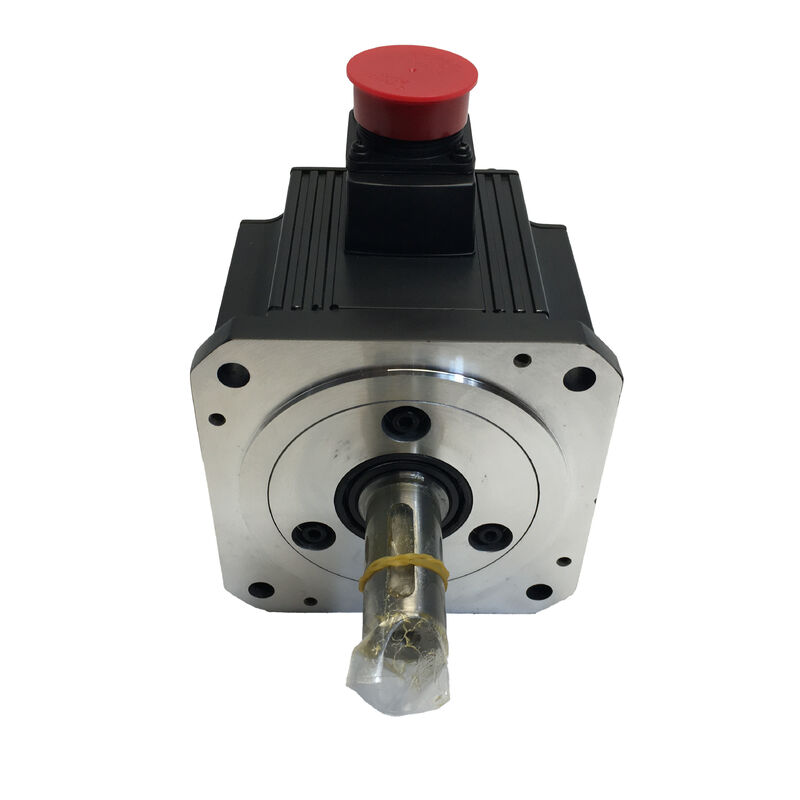
Mitsubishi HC-SFE52 | HC-SF Series Medium Inertia AC Servo Motor — 0.5kW, 2.39Nm, 2000RPM, 126V, 3.2A, 130×130mm Flange, IP65
Part Number: HC-SFE52
Series: MELSERVO HC-SF Series — Medium Inertia, Medium Capacity AC Servo Motor
Rated Output: 0.5 kW (500 W)
Rated Torque: 2.39 Nm
Peak Torque: 7.16 Nm
Rated Speed: 2,000 RPM
Input: 3-Phase AC, 126 V
Rated Current: 3.2 A
Inertia Class: Medium
Flange Size: 130 × 130 mm
Ingress Protection: IP65
Compatible Amplifier: MR-J2S Series (MR-J2S-100A/B)
Condition: New / Refurbished / Surplus
Overview
The Mitsubishi HC-SFE52 is a 0.5 kW medium inertia AC servo motor from the HC-SF series, operating at 2,000 RPM rated speed on a three-phase 126V input with 3.2A rated current. At 2.39 Nm rated torque and a 7.16 Nm peak — a 3:1 peak-to-rated ratio that provides strong acceleration capability relative to the continuous rating — it sits in the medium capacity bracket of the HC-SF family: substantial enough for primary feed axis and material handling work, compact enough for machines where the 130 × 130 mm flange footprint is the dimensional constraint.
The HC-SF series occupies a distinct position in Mitsubishi's servo motor lineup: medium inertia, 2,000 RPM rated operation, and the larger 130 × 130 mm flange that handles the heavier loads and larger coupling geometry typical of mid-range machine tool and industrial automation applications.
This is in contrast to the smaller-flange HF and HC-KF/HC-MF families, which run at 3,000 RPM on 60 × 60 mm or 80 × 80 mm flanges for lighter loads. The HC-SFE52's 2,000 RPM ceiling and medium inertia rotor make it more tolerant of heavier load inertia ratios, more stable on poorly damped mechanical structures, and less prone to the resonance sensitivity that low-inertia designs can exhibit when the load inertia is not tightly controlled.
Built to IP65, the HC-SFE52 provides complete dust exclusion and jet-water resistance across the motor body — appropriate for the machine tool environments, conveyor systems, and industrial machinery where the HC-SF series is most commonly applied.
Key Specifications
| Parameter |
Value |
| Rated Output |
0.5 kW (500 W) |
| Rated Torque |
2.39 Nm |
| Peak Torque |
7.16 Nm |
| Rated Speed |
2,000 RPM |
| Motor Input |
3-Phase AC, 126 V |
| Rated Current |
3.2 A |
| Inertia Class |
Medium |
| Flange Size |
130 × 130 mm |
| Ingress Protection |
IP65 |
| Compatible Amplifier |
MR-J2S-100A/B |
| Operating Temperature |
0°C to +40°C |
| Series |
MELSERVO HC-SF |
Medium Inertia at 2,000 RPM — Why This Design Class Exists
The 2,000 RPM rated speed of the HC-SF series, compared to the 3,000 RPM norm for the smaller HF and HC-KF families, reflects a deliberate design choice: the medium inertia, larger-frame motor produces its rated torque at a lower speed ceiling, which is advantageous for axis configurations where the ball screw pitch, gear ratio, or direct coupling arrangement results in a motor running speed in the 500–2,000 RPM range during normal operation.
Machine tool feed axes on machining centres and turning centres with medium to large table masses are the natural application territory.
The table inertia reflected back through the ball screw and coupling to the motor shaft is substantial — on a machine with a 200 kg table and a 10mm pitch ball screw, the reflected inertia at the motor can easily reach 5–15 times the motor's own rotor inertia.
A low inertia motor would demand extremely precise gain tuning to remain stable at this inertia ratio; the medium inertia HC-SFE52 absorbs this loading with more margin before servo instability becomes a concern.
The same characteristic benefits robotic arms, rotary index tables, and winding/tension control systems where the load inertia is inherently variable across the operating cycle and the servo must remain stable throughout.
The medium inertia rotor acts as a stabilising flywheel in the servo loop, smoothing the velocity response at transitions between light and heavy load conditions.
2.39 Nm Rated and 7.16 Nm Peak — The Torque Reserve
The 3:1 ratio between peak and rated torque is a defining characteristic of the HC-SF series at this capacity level. In continuous operation, the motor delivers 2.39 Nm — sufficient to overcome friction, cutting forces, and gravitational loads during steady-state movement.
During acceleration from rest to commanded velocity, the available 7.16 Nm peak torque provides the impulse current to change the load's angular velocity rapidly, enabling short acceleration phases and fast cycle times.
This peak torque reserve is available for a defined duty cycle — not continuously.
The servo amplifier's electronic thermal protection monitors the RMS current demand over time and trips on overload if the motor is driven beyond its thermal capacity sustained. The MR-J2S amplifier's overload protection curve defines the boundary: brief excursions to peak torque are permitted; sustained operation above rated torque is not.
For axis sizing, the accelerating torque requirement determines whether the 7.16 Nm peak is sufficient for the intended move profile.
The calculation — load inertia, move distance, time available, friction torque — establishes the peak torque demand. If the required acceleration torque exceeds the HC-SFE52's 7.16 Nm peak, the next model up in the HC-SF series (HC-SFE102, 1.0 kW, 4.78 Nm rated, 14.3 Nm peak) must be considered.
130 × 130 mm Flange — Mechanical Integration
The 130 × 130 mm mounting flange of the HC-SFE52 is the standard format for medium-capacity servo motor integration in machine tools and industrial automation. It provides the bolt pattern and spigot register geometry that machine tool builders and equipment designers have standardised around for this power class — the same mechanical interface shared by the HC-SFS52, HC-SFS102, and other motors in the HC-SF and successor series.
For replacement and retrofit applications, the 130 × 130 mm flange means the HC-SFE52 can physically replace or be replaced by any motor in the same flange class without mechanical modification to the machine. The key alignment features — the register diameter that centres the motor in the housing bore, the bolt circle and bolt hole pattern — are standardised across this motor class.
The shaft diameter and coupling geometry must also match, but the flange interface itself is a common format.
The 130 mm format is substantially larger than the 60 mm and 80 mm flanges used on the smaller HF-KE and HF-SP series.
This physical scale reflects the mechanical loads the HC-SFE52 is designed to handle: higher radial shaft loads from belt drives and gear meshes, larger coupling hubs with more clamping surface area, and the structural stiffness required when the motor and load are separated by a coupling flexible element rather than rigidly connected.
IP65 Protection and the HC-SF Application Environment
IP65 is complete dust exclusion plus protection against water jets from any direction — a robust environmental standard that reflects the HC-SF series' design for machine tool and industrial automation environments where coolant, cleaning water, and machining swarf are present in the working area near the servo motor.
At 0.5 kW and the 130 × 130 mm scale, the HC-SFE52 is most commonly installed as a primary feed axis motor on machining centres and turning centres, a conveyor positioning drive, or a rotary index table axis — all environments where the motor body can be exposed to coolant mist during machining or direct cleaning during maintenance. The IP65 rating covers these conditions reliably.
What IP65 does not protect against is direct sustained immersion or pressurised coolant directed at the shaft gap — the HC-SF series is designed for splash and jet protection, not continuous fluid immersion.
Applications where the motor is submerged or where high-pressure coolant is directed continuously at the shaft require the oil seal variant or a purpose-built wash-down specification motor.
MR-J2S Series Compatibility
The HC-SFE52 is designed for use with the MR-J2S series servo amplifiers — specifically the MR-J2S-100A (analogue/pulse interface) or MR-J2S-100B (SSCNET network interface) for this 0.5 kW motor.
The MR-J2S platform, part of Mitsubishi's MELSERVO-J2-Super generation, provides position, speed, and torque control modes, auto-tuning, and the RS-232C/RS-422 communication interface for parameter setting and monitoring via MR Configurator software.
The HC-SF series uses cannon-type (MS-type) connectors for both the motor power cable and the encoder cable — a robust circular connector format that provides secure engagement and reliable vibration resistance in machine tool installations.
When replacing or reconnecting the HC-SFE52, the connector engagement must be confirmed to be complete and the locking ring fully seated; cannon connectors that are partially engaged will provide intermittent electrical contact that presents as erratic servo behaviour or encoder alarm codes rather than an obvious connection fault.
For customers with MR-J2S amplifiers in existing installations, the HC-SFE52 is a confirmed compatible motor at the 0.5 kW, 2000 RPM class. Equipment upgrading from MR-J2S to MR-J4 amplifiers should note that migration paths exist using Mitsubishi's renewal tools, maintaining the existing MR-J2S-B motion controller connection while transitioning to MR-J4-B amplifiers and compatible motors.
FAQ
Q1: What is the difference between the HC-SFE52 and the HC-SFS52?
Both are 0.5 kW, 2,000 RPM medium inertia HC-SF series motors with the same rated torque, peak torque, current, and 130 × 130 mm flange. The difference is the encoder generation.
The HC-SFS52 belongs to the MELSERVO J2S series and carries a 17-bit absolute encoder at 131,072 ppr — adding a battery to the MR-J2S amplifier enables absolute position retention without homing at startup.
The HC-SFE52 is the earlier HC-SF series variant with its respective encoder configuration. For replacement purposes, confirm both the encoder interface compatibility with the installed amplifier and the mechanical configuration (shaft type, oil seal presence) before substituting one variant for the other.
Q2: Does the HC-SFE52 need a reference return (homing) at each startup?
This depends on the encoder variant and amplifier configuration. The HC-SFS52 (the J2S-series equivalent) uses an absolute encoder that, with a battery fitted to the MR-J2S amplifier, retains position data through power loss — eliminating the homing requirement.
Whether the HC-SFE52's encoder provides absolute capability should be confirmed from the motor's documentation or nameplate. If the installed encoder is incremental, a homing cycle is required at each power cycle.
For machines where startup time is operationally significant, confirming the absolute encoder capability is an important commissioning question.
Q3: What is the load-to-motor inertia ratio recommendation for the HC-SFE52?
For the HC-SF medium inertia series, Mitsubishi's guidance typically allows load inertia ratios up to 15 times the motor's own rotor inertia for stable servo operation at the recommended gain settings.
The medium inertia design is specifically more tolerant of high inertia ratios than low-inertia motors, which is one of the primary reasons for specifying it on axes with heavy tables, large workpieces, or transmission elements that reflect significant inertia to the motor shaft.
If the load inertia ratio exceeds Mitsubishi's recommendation, contact Mitsubishi for guidance on gain settings and any application limitations.
Q4: Which MR-J2S amplifier is required for the HC-SFE52?
The HC-SFE52 at 0.5 kW is matched with the MR-J2S-100A (analogue/pulse command interface) or MR-J2S-100B (SSCNET serial network interface). The "100" in the amplifier designation indicates the 100W class capacity bucket, which covers 0.5 kW motors in the Mitsubishi amplifier sizing convention for this series.
Confirm the control interface type — whether the machine uses individual pulse/analogue axis commands (A-type) or a motion controller over SSCNET (B-type) — before ordering the amplifier.
Q5: What are the most important inspection points when evaluating a used HC-SFE52?
Rotate the shaft by hand for bearing smoothness — the 130 mm frame carries larger bearings than smaller motors, and any roughness or grinding is audible before it becomes mechanically severe.
Inspect the cannon connectors for bent or corroded pins; the encoder connector is the most critical — even mild pin corrosion increases contact resistance and causes intermittent feedback errors.
Measure three-phase winding resistance for balance and check insulation resistance to earth with a megger. Inspect the shaft for fretting or scoring from previous coupling installations, particularly at the keyway or coupling engagement zone.
A bench run-up to 2,000 RPM on a compatible MR-J2S amplifier with torque monitoring and encoder feedback verified is the correct final check before installation on a production machine.

 Your message must be between 20-3,000 characters!