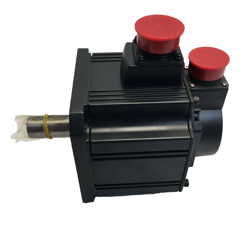
Mitsubishi HC-SFE102 | HC-SF Series Medium Inertia AC Servo Motor — 1.0kW, 4.78Nm, 2000RPM, 123V, 6.0A, IP65, Class F, 7.3kg
Part Number: HC-SFE102 (also HCSFE102)
Series: MELSERVO HC-SF Series — Medium Inertia, Medium Capacity AC Servo Motor
Rated Power Output: 1,000 W (1.0 kW)
Rated Torque: 4.78 Nm
Peak Torque: 14.3 Nm
Rated Speed: 2,000 RPM
Rated Voltage Input: 123 VAC
Rated Current Input: 6.0 A
Weight: 7.3 kg
Insulation Class: F (155°C)
Ingress Protection: IP65
Flange Size: 130 × 130 mm
Compatible Amplifier: MR-J2S Series
Condition: New / Refurbished / Surplus
Overview
The Mitsubishi HC-SFE102 is a 1.0 kW medium inertia AC servo motor from the HC-SF series, rated at 2,000 RPM on a 123V three-phase input with 6.0A rated current.
At 4.78 Nm rated torque and 14.3 Nm peak, it provides the torque density and physical scale — 130 × 130 mm flange, 7.3 kg — that mid-range machine tool feed axes, conveyor positioning drives, and industrial automation equipment at the 1 kW class require.
The HC-SFE102 is the 1 kW member of the HC-SF family, stepping directly above the 0.5 kW HC-SFE52 in the same series. Both motors share the same 130 × 130 mm mounting footprint and the same 2,000 RPM rated speed, which means a machine designed around either motor can accommodate the other with mechanical interchangeability at the flange — only the electrical connections, amplifier sizing, and servo parameters differ.
For an application where load analysis confirms that 1.0 kW and 4.78 Nm continuous torque are required rather than the 0.5 kW / 2.39 Nm of the HC-SFE52, the HC-SFE102 provides that step up within the identical mechanical envelope.
Class F insulation — rated to 155°C — provides the thermal headroom that continuous-duty industrial operation demands.
The motor can sustain periods of above-rated loading without the winding temperature reaching a level that initiates insulation degradation, giving both the motor and the system designers a genuine margin against thermal failure under the kind of variable-duty cycles that real production machines impose.
Key Specifications
| Parameter |
Value |
| Rated Power Output |
1,000 W (1.0 kW) |
| Rated Torque |
4.78 Nm |
| Peak Torque |
14.3 Nm |
| Rated Speed |
2,000 RPM |
| Rated Voltage Input |
123 VAC |
| Rated Current Input |
6.0 A |
| Weight |
7.3 kg |
| Insulation Class |
F (155°C) |
| Ingress Protection |
IP65 |
| Flange Size |
130 × 130 mm |
| Inertia Class |
Medium |
| Compatible Amplifier |
MR-J2S Series |
1.0 kW in the HC-SF Series — Doubling the Capacity at the Same Footprint
Moving from the HC-SFE52 (0.5 kW) to the HC-SFE102 (1.0 kW) within the HC-SF family doubles the rated output while keeping the mounting interface — the 130 × 130 mm flange, the bolt circle, and the register diameter — identical.
The motor body grows in depth to accommodate the additional winding volume and the larger rotor that produces twice the rated torque, but the footprint seen by the machine's motor mounting face is unchanged.
This is a practical benefit for machine builders who need to offer a product line with multiple capacity options.
A single mechanical design with a 130 mm motor mounting can accept either the HC-SFE52 at 0.5 kW or the HC-SFE102 at 1.0 kW, covering a 2:1 output range without modifying the machine's structural design. The electrical connections, amplifier, and software parameters change; the mechanical drawing does not.
At 4.78 Nm rated torque, the HC-SFE102 covers primary feed axes on mid-sized machining centres where the table mass and cutting forces require more torque authority than a 0.5 kW motor can sustain.
On a machining centre with a 100–200 kg table and a 10mm ball screw at 1:1 coupling, the rated and peak torque of the HC-SFE102 provides adequate force for aggressive cutting cycles without operating the motor continuously near its thermal limit.
4.78 Nm Rated / 14.3 Nm Peak — The Working Torque Range
The 3:1 peak-to-rated ratio in the HC-SF series gives the HC-SFE102 three times its continuous torque capability available for acceleration phases. In practical terms: the motor carries the axis load and overcomes cutting resistance at 4.78 Nm or less in steady-state; during acceleration from rest to rapid traverse speed, 14.3 Nm is available to change the load's velocity in the shortest possible time.
The time over which peak torque can be sustained before the amplifier's electronic thermal model trips is limited by the RMS current calculation.
At 6.0A rated, peak current for 14.3 Nm is approximately 18A — the amplifier monitors RMS current over a rolling window and allows brief peaks while preventing the average current from exceeding the motor's thermal capacity.
A correctly sized motion profile for the HC-SFE102 keeps the RMS torque below 4.78 Nm while using the peak torque for the shortest acceleration phases the application allows.
For applications with step changes in load torque — a conveyor that encounters variable back-pressure from material weight, or a machine axis that transitions between air cutting and material engagement — the peak torque reserve provides the current headroom to absorb these transients without the servo falling into following error.
Class F Insulation — 155°C Thermal Ceiling
The HC-SFE102's Class F winding insulation is rated to a thermal endurance of 155°C at the hotspot. In normal operation at rated current, ambient temperature, and adequate ventilation, the winding temperature stays well below this limit.
The Class F rating creates a genuine thermal buffer — it means the motor can sustain intermittent overloads, elevated ambient temperatures, or restricted airflow conditions without the winding temperature approaching the level at which insulation degradation becomes rapid.
Insulation life halves with each sustained 10°C of temperature above the rated class limit. A motor running 20°C over its insulation class rating has approximately one quarter of its nominal insulation life.
Class F at 155°C, operating in a 40°C ambient with a correctly sized amplifier driving it at rated load, will have a winding temperature typically 60–80°C above ambient — leaving a 35–55°C margin below the class limit under normal conditions.
This margin matters in two specific scenarios: machines that operate in elevated ambient environments (foundries, summer production without climate control, enclosed cabinets with inadequate airflow), and machines that cycle between idle and full-load rapidly.
In both cases, Class F provides the thermal reserve that allows the HC-SFE102 to absorb heat bursts without the insulation experiencing degrading temperatures.
IP65 and the Machine Tool Environment
IP65 — complete dust exclusion and protected against water jets from any direction — is the minimum practical requirement for a servo motor operating on or near a CNC machine tool's working area.
Coolant mist, condensation from cold parts and warm air, cleaning jets, and the fine metallic and abrasive particles generated by machining are all present in these environments at varying intensities, and a motor without adequate protection would require replacement on a timescale measured in months rather than years.
The HC-SFE102's IP65 rating means the motor body, winding, and encoder compartment are sealed against these conditions.
The shaft exit is the one gap that IP65 testing does not seal completely — the rotating shaft must pass through the motor front endshield, and the annular gap at this point is the pathway for lubricant mist from adjacent ball screws and bearings to migrate into the motor body over time. For installations near lubricated mechanisms, the oil seal variant of the HC-SF series adds a lip seal at the shaft exit to close this pathway.
Where the motor is mounted away from direct coolant exposure — inside a secondary enclosure, on a machine axis well above the cutting zone — the standard IP65 specification is adequate.
Where the motor body is in the primary machine working zone, in proximity to coolant delivery nozzles, or where the motor is hosed down during cleaning, the oil seal variant is the conservative and correct selection.
7.3 kg — Physical Scale and Installation Considerations
At 7.3 kg, the HC-SFE102 is a motor that requires conscious mechanical handling during installation and maintenance.
This weight — roughly 60% heavier than a comparable 1 kW motor in the smaller 80 mm flange class — reflects the larger rotor, longer stator stack, and heavier housing that the 130 mm flange medium inertia format requires to produce 4.78 Nm continuous torque at 2,000 RPM.
In installation practice, 7.3 kg means the motor should not be supported only by its electrical connectors while the mounting bolts are tightened — connector damage and misalignment at the motor register are both risks when the motor's weight is carried through an unsupported cable loom.
A support block or a second person holding the motor while the first aligns and torques the mounting bolts is the correct installation practice.
On the machine, the 7.3 kg mass also contributes to the axis' mechanical resonance characteristics.
The motor, its coupling, and the driven mechanism form a combined dynamic system, and changes in the motor mass — for instance, replacing a lighter motor with the HC-SFE102, or vice versa — require re-evaluation of the servo gain settings and potentially the mechanical compliance of the coupling between motor and ball screw.
MR-J2S Series Amplifier Compatibility
The HC-SFE102 is designed for use with Mitsubishi's MR-J2S series servo amplifiers. At 1.0 kW and 6.0A rated current, the matched amplifier is the MR-J2S-100A (analogue/pulse train interface) or MR-J2S-100B (SSCNET serial network interface).
The HC-SF series motors use cannon-type (MS-type) circular connectors for the power and encoder cables — a connector format that provides reliable vibration-resistant engagement in machine tool installations, but one that requires the locking ring to be fully engaged before the motor is operated.
A partially seated cannon connector presents as encoder fault alarms or intermittent axis errors rather than an obvious connection problem.
The MR-J2S platform supports position, speed, and torque control modes, auto-tuning, and the RS-232C/RS-422 serial communication interface for parameter setting via MR Configurator software.
For installations transitioning from MR-J2S to newer amplifier generations, Mitsubishi's renewal tools support migration to MR-J4-B amplifiers using the existing MR-J2S-B motion controller, allowing the drive electronics to be upgraded while the motor and mechanical interface remain unchanged.
FAQ
Q1: What is the difference between the HC-SFE102 and the HC-SFS102?
Both are 1.0 kW, 2,000 RPM, medium inertia HC-SF series motors with the same 130 × 130 mm flange, 4.78 Nm rated torque, and MR-J2S amplifier compatibility.
The HC-SFS102 belongs to the MELSERVO J2S series and carries a 17-bit absolute encoder at 131,072 ppr — with a battery fitted at the amplifier, it provides absolute position retention through power loss, eliminating homing at startup.
The HC-SFE102 is the earlier HC-SF series variant with the encoder configuration of its generation. When sourcing a replacement, confirm the encoder interface is compatible with the installed amplifier before substituting one variant for the other.
Q2: The rated voltage is listed as 123V — is this a single-phase or three-phase motor?
The HC-SFE102 is a three-phase AC servo motor. The 123V rating is the motor's rated voltage — the back-EMF voltage at which the stator windings are designed to operate when the amplifier drives the motor at rated speed.
This is not the supply voltage to the amplifier; the supply voltage is 200–230V three-phase to the MR-J2S amplifier, which then generates the variable-frequency variable-voltage output to drive the motor.
The 123V motor voltage appears on the motor nameplate and is used for motor parameter verification, not for supply wiring calculations.
Q3: What does Class F insulation mean for service life and operating conditions?
Class F insulation is thermally rated to 155°C winding temperature. In normal operation — rated load, 40°C ambient, adequate ventilation — the winding operates significantly below this limit, providing a thermal margin against overload transients and elevated ambient conditions.
Insulation life degrades exponentially with temperature: sustained operation at 155°C halves life compared to sustained operation at 145°C. The Class F rating allows the HC-SFE102 to sustain brief overloads and elevated ambients without approaching the thermal boundary where degradation becomes rapid.
Q4: Does the HC-SFE102 require homing at each startup?
This depends on the encoder variant fitted. The HC-SFE (earlier HC-SF series) generation used an incremental encoder in some configurations, which would require a homing cycle after each power cycle. The HC-SFS102 (J2S series) carries an absolute encoder that retains position through power loss.
If the installed HC-SFE102 has an incremental encoder, a homing traverse is required at startup to establish position reference.
If absolute encoder capability is important for the application — avoiding homing on restart after E-stop or power loss — the HC-SFS102 with battery-backed absolute position is the appropriate specification.
Q5: What are the key checks when installing or evaluating a used HC-SFE102?
Rotate the shaft by hand and listen for bearing smoothness — the 7.3 kg motor carries larger bearings than smaller-frame motors, and bearing roughness is detectable as tactile resistance or audible grinding well before it becomes mechanically severe.
Inspect the cannon connector pins on both power and encoder cables for corrosion or bent contacts. Measure three-phase winding resistance across all phase pairs for balance, and check insulation resistance to earth with a megger; 6.0A rated current in a medium-capacity motor generates real heat, and winding insulation condition is worth verifying before installation.
Inspect the shaft surface for fretting or scoring from previous coupling installations. On a test run connected to a compatible MR-J2S amplifier, monitor following error, confirm current at no load is within expected bounds, and verify encoder feedback over a full rotation before committing the motor to production duty.

 Your message must be between 20-3,000 characters!