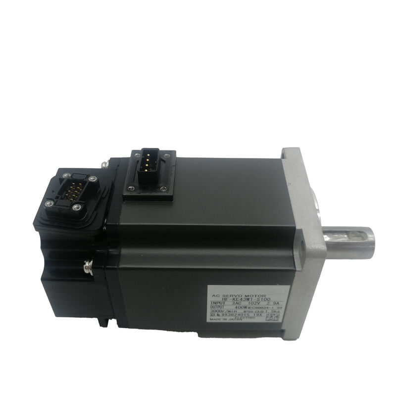
Mitsubishi HF-KE43W1-S100 | Low Inertia AC Servo Motor — 400W, 1.3Nm, 3000RPM Rated / 4500RPM Max, Straight Shaft, No Brake, 131072 ppr, MR-E Series
Part Number: HF-KE43W1-S100
Series: MELSERVO HF-KE — Low Inertia, Small Capacity AC Servo Motor
Rated Output: 400 W (0.4 kW)
Power Facility Capacity: 0.9 kVA
Rated Torque: 1.3 Nm (184 oz·in)
Peak Torque: 3.8 Nm (538 oz·in)
Rated Speed: 3,000 RPM
Maximum Speed: 4,500 RPM
Shaft Type: Standard Straight (Plain, No Keyway)
Electromagnetic Brake: None
Encoder: Incremental, 131,072 ppr (17-bit)
Supply Voltage: 200 VAC Class (3-Phase)
Compatible Amplifier: MR-E Series (Super MR-E / S100)
Condition: New
Overview
The Mitsubishi HF-KE43W1-S100 is a 400W low inertia AC servo motor from the HF-KE series, configured with a standard straight plain shaft, no electromagnetic brake, and a 131,072 ppr incremental encoder for the Super MR-E amplifier platform.
Three specifications define this unit's operating envelope and installation character: rated torque of 1.3 Nm with a 3.8 Nm peak for positioning dynamics, a 3,000 RPM rated speed with a 4,500 RPM ceiling, and a plain straight shaft that transmits torque entirely through friction clamping at the coupling interface.
The 4,500 RPM maximum speed on the W1-S100 is worth noting explicitly — it is lower than the 6,000 RPM ceiling found on some other HF-KE43 variants.
In practice, most light-load positioning applications operate well within 3,000–4,000 RPM during rapid traverse, and the W1-S100's speed range covers these comfortably.
Where the speed requirement approaches or exceeds 4,500 RPM continuously, a different variant with a higher maximum speed rating must be selected.
Within its rated envelope, however, the HF-KE43W1-S100 delivers the full 1.3 Nm rated torque across the continuous speed range, with the 3.8 Nm peak available for acceleration phases throughout.
At 0.9 kVA power facility capacity, the electrical supply demand this motor places on the facility — through the MR-E-40A amplifier — is modest.
This figure reflects the total input power drawn from the mains during rated operation, including amplifier losses, and determines the circuit breaker and supply wiring sizing for the drive cabinet.
Key Specifications
| Parameter |
Value |
| Rated Output |
400 W (0.4 kW) |
| Power Facility Capacity |
0.9 kVA |
| Rated Torque |
1.3 Nm (184 oz·in) |
| Peak Torque |
3.8 Nm (538 oz·in) |
| Rated Speed |
3,000 RPM |
| Maximum Speed |
4,500 RPM |
| Shaft Type |
Standard Straight Plain (No Keyway) |
| Electromagnetic Brake |
None |
| Encoder |
Incremental, 131,072 ppr (17-bit) |
| Supply Voltage |
200 VAC class, 3-phase |
| Compatible Amplifier |
MR-E Series (S100 connector) |
Straight Plain Shaft — Clamping-Only Torque Transmission
The W1 configuration carries a standard straight shaft with no keyway. At 1.3 Nm rated torque — and 3.8 Nm peak during acceleration — the coupling must transmit all torque through friction between the shaft surface and the bore of whatever component mounts to it: a timing pulley, a coupling hub, a pinion, or a collar. There is no mechanical interlock to assist.
This is entirely adequate when the coupling is correctly specified and installed.
The hub bore must be machined to the correct fit tolerance for the shaft diameter, the hub must be tightened to the coupling manufacturer's specified clamping torque using a calibrated tool, and the shaft and bore surfaces must be clean and undamaged before assembly.
These conditions met, a plain shaft coupling on a 400W motor carries the torque load without issue through the normal service life of the machine.
The practical advantage of the plain straight shaft over a keyed configuration is assembly flexibility.
There is no angular alignment constraint between shaft and hub — the hub can be positioned at any rotational position before clamping, which simplifies the assembly of timing pulleys and similar components where the belt path determines the ideal hub orientation.
It also makes hub removal straightforward: loosen the clamping screw or nut, and the hub slides off without the need to first extract a key.
The potential risk is coupling slip under conditions that exceed the friction clamping torque — sustained vibration, alternating direction reversals, or any situation where the peak torque demand approaches the coupling's slip threshold.
On a 400W servo axis with defined load characteristics and a correctly specified coupling, this risk is managed through proper engineering at the design stage.
If the application involves high-frequency direction reversals with significant inertia, or if the peak torque at the coupling regularly approaches the clamping limit, the keyed shaft variant (HF-KE43KW1-S100) provides a positive rotational interlock that eliminates this risk entirely.
4,500 RPM Maximum Speed — Operating Within the Envelope
The HF-KE43W1-S100's 4,500 RPM maximum speed defines the upper mechanical and electrical limit for continuous operation. Exceeding this speed — even briefly — risks motor bearing overload, encoder pulse counting errors at frequencies beyond the encoder's rated maximum output, and electrical overspeed alarms at the MR-E amplifier.
The rated speed of 3,000 RPM is where the motor delivers its full rated torque of 1.3 Nm; between 3,000 and 4,500 RPM the motor operates in the field-weakening region where available torque reduces as speed increases.
For most light-load positioning applications, the operating profile stays well within the 4,500 RPM limit. A 400W low inertia motor is most commonly applied to axes that spend the majority of their cycle time in positioning moves at moderate speed — typically 500 to 3,000 RPM depending on the ball screw pitch, transmission ratio, and required table velocity. Rapid traverse moves may briefly push toward the higher speed end, but sustained operation near 4,500 RPM is unusual in standard positioning duty.
The 4,500 RPM ceiling does matter when calculating maximum table velocity.
At 3,000 RPM motor speed with a 1:1 transmission and 10mm ball screw pitch, the table moves at 500 mm/min — well within typical CNC rapid traverse. If the application requires significantly higher traverse speeds, the transmission ratio and screw pitch must be confirmed against the 4,500 RPM limit before specifying this variant.
131,072 ppr Incremental Encoder and MR-E Auto-Tuning
The 17-bit incremental encoder returns 131,072 pulses per revolution to the MR-E amplifier's position control loop. This resolution gives the amplifier fine-grained velocity and position feedback, which it uses in two ways.
First, it enables tight position loop closure: at the moment the motor decelerates toward a target position, the amplifier can detect very small following errors and generate corrective torque commands before the error becomes visible as a positioning inaccuracy.
At 131,072 ppr, the position increment per pulse at a 10mm pitch ball screw with 1:1 coupling is approximately 0.076 μm — finer than any practical machine tool's mechanical accuracy, so the encoder is not limiting the achievable positioning resolution in any real installation.
Second, the high pulse count supports the MR-E's real-time auto-tuning.
Auto-tuning observes the velocity following error during normal operation and progressively adjusts the servo gains — position loop gain, speed loop gain, integral gain — to minimise the error without introducing oscillation.
The process begins automatically when the servo is enabled and continues in the background as the machine runs. For a 400W motor on a light positioning axis, auto-tuning typically converges on stable, well-matched settings within the first few machine cycles, eliminating the need for manual gain optimisation at commissioning.
Since the encoder is incremental rather than absolute, a reference return (homing) cycle is required at each power cycle to establish the axis position reference.
The axis traverses to a reference switch or mechanical stop at reduced speed, the amplifier registers the encoder count at the reference position, and the coordinate system is established from that point.
This is an automatic machine startup sequence on most Mitsubishi-controlled systems and adds typically 5 to 30 seconds to startup time depending on the axis stroke and homing speed setting.
S100 Connector and MR-E Amplifier — System Wiring Practicality
The S100 designation identifies the motor connector configuration as the Super MR-E interface. On the MR-E amplifier, the power and encoder connectors exit from the front face of the unit — a design that simplifies cable routing when the amplifier is mounted in a panel with limited side and top clearance.
Cable runs from the amplifier front face to the motor power and encoder connectors can follow a direct path without routing around the amplifier body.
The MR-E-40A servo amplifier provides two control interfaces in a single unit: pulse train input for position and speed control from a CNC or PLC pulse output, and analogue input (±10V) for speed and torque control.
Both are available without any hardware change, making the HF-KE43W1-S100 / MR-E-40A combination usable in either pulse-command or analogue-command machine architectures. Control mode is selected by parameter and wiring configuration.
Built-in protective functions in the MR-E-40A cover overcurrent shutdown, regenerative overvoltage shutdown, overload protection via electronic thermal relay, encoder fault protection, overspeed protection at 4,500 RPM, and excessive position error protection.
The overspeed protection specifically enforces the W1-S100's 4,500 RPM mechanical limit at the amplifier level, preventing accidental operation above the rated maximum speed regardless of the command source.
FAQ
Q1: What is the difference between the HF-KE43W1-S100 and the HF-KE43KW1-S100?
Both are 400W HF-KE series motors for the Super MR-E amplifier with the same rated torque, speed, encoder, and power ratings. The difference is the shaft: the HF-KE43W1-S100 has a standard straight plain shaft with no keyway, transmitting torque through friction clamping only.
The HF-KE43KW1-S100 has a keyed shaft, adding a positive rotational interlock between shaft and coupling hub.
The keyed variant is preferred for axes with frequent high-frequency direction reversals or where sustained peak torque loads could overcome the friction clamping of a plain shaft. For clean, moderate-duty positioning axes with correctly specified couplings, the plain shaft W1 variant is fully adequate.
Q2: The maximum speed is listed as 4,500 RPM. Does this limit rapid traverse speed?
Yes, in proportion to the mechanical transmission. At 4,500 RPM motor speed with a 1:1 coupling to a 10mm pitch ball screw, maximum table velocity is 45 m/min. For most 400W axis applications — light positioning, small conveyor drives, electronic assembly — this is well above the required rapid traverse speed.
If the application requires higher traverse speeds, the transmission ratio, screw pitch, and required motor RPM must be calculated to confirm the 4,500 RPM limit is not exceeded in normal operation.
Q3: Does the HF-KE43W1-S100 require a reference return (homing) at each power cycle?
Yes. The incremental encoder has no stored position memory — position is known only relative to a reference point established by a homing cycle at startup.
The MR-E amplifier performs this automatically at startup on most machine configurations: the axis moves to a reference switch at reduced speed, the encoder count at that position is registered, and the coordinate system is established.
If power is interrupted mid-cycle, the homing cycle must restart from the beginning when power is restored. Machines where frequent power interruptions would make this operationally inconvenient should consider an absolute encoder variant.
Q4: What is the 0.9 kVA power facility capacity figure used for?
The power facility capacity is the total AC input demand from the facility supply when the motor and amplifier are operating at rated output — including amplifier losses. It is used to size the circuit breaker, contactor, supply wiring, and the panel's total power budget when multiple drives share a common supply.
At 0.9 kVA, the HF-KE43W1-S100 / MR-E-40A combination draws approximately 0.9 kVA from the 200 VAC supply at full rated load. The actual demand is lower during partial load operation, which is typical for a positioning axis that runs at rated torque only during acceleration and deceleration phases.
Q5: How should the coupling be installed on the plain straight shaft?
Clean both the shaft surface and the hub bore thoroughly — any contamination reduces the effective friction coefficient and therefore the clamping torque capacity. Confirm the hub bore diameter matches the shaft diameter to the correct fit specification (typically a light interference or close clearance fit for servo motor couplings).
Apply the hub to the shaft, position it at the correct axial location, and tighten the clamping screw or nut to the torque specified by the coupling manufacturer using a calibrated torque wrench — not by feel. After initial installation and a brief run cycle, recheck the clamping torque, as minor settling at the interface is normal. Mark the relative position of shaft and hub before each maintenance access so any rotational slip can be detected visually on reassembly.


 Your message must be between 20-3,000 characters!