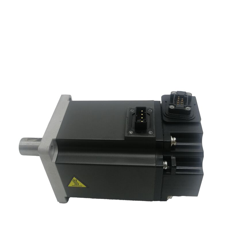
Mitsubishi HF-KE73W1-S100 | Low Inertia AC Servo Motor — 0.75kW, 2.4Nm Rated / 7.2Nm Peak, 3000RPM, 19mm Plain Shaft, No Brake, MR-E Series
Part Number: HF-KE73W1-S100
Series: MELSERVO HF-KE — Low Inertia, Small Capacity AC Servo Motor
Rated Output: 0.75 kW (750 W)
Rated Torque: 2.4 Nm
Peak Torque: 7.2 Nm
Rated Speed: 3,000 RPM
Maximum Speed: 6,000 RPM
Maximum Current: 14 A
Shaft Type: Standard Straight Plain (No Keyway), 19h6 mm diameter
Rotor Inertia: 1.63 × 10⁻⁴ kg·m²
Electromagnetic Brake: None
Flange Size: 80 × 80 mm
Dimensions: H80 × W80 × D153.8 mm
Operating Temperature: 0°C to +40°C
Compatible Amplifier: MR-E Series (Super MR-E / S100)
Ingress Protection: IP65
Condition: New
Overview
The Mitsubishi HF-KE73W1-S100 is a 0.75 kW low inertia AC servo motor from the HF-KE series, configured with a 19mm standard straight plain shaft, no electromagnetic brake, and a 131,072 ppr absolute encoder for the Super MR-E amplifier platform. At 2.4 Nm rated torque, 7.2 Nm peak, and 3,000 RPM continuous rated speed with a 6,000 RPM ceiling, it is the top of the HF-KE compact range — sitting above the HF-KE43 (0.4 kW) while sharing the same 80 × 80 mm flange footprint.
The W1 suffix identifies the plain straight shaft without keyway. The shaft diameter is 19h6 mm — a larger diameter than the smaller HF-KE motors in the same series, reflecting the higher torque this motor must transmit at the shaft interface.
At 2.4 Nm rated and 7.2 Nm peak, the coupling arrangement must be specified to handle the full peak torque through friction clamping alone: no key provides a positive rotational interlock, so the entire mechanical engagement depends on the clamping force the hub generates on the 19mm shaft surface.
Correctly sized and installed, this is entirely reliable; the specification choice between plain and keyed shaft (the W1 vs KW1 variants) comes down to the application's assembly requirements and torque impulse characteristics.
The rotor inertia of 1.63 × 10⁻⁴ kg·m² confirms the low inertia classification — the rotor is light, which means it changes velocity quickly in response to amplifier current commands. Combined with the 7.2 Nm peak available for acceleration, the HF-KE73W1-S100 can reach 3,000 RPM from standstill in a very short time on light loads, producing the snappy, fast-settling positioning response that high-throughput automation cycles demand.
Key Specifications
| Parameter |
Value |
| Rated Output |
0.75 kW (750 W) |
| Rated Torque |
2.4 Nm |
| Peak Torque |
7.2 Nm |
| Rated Speed |
3,000 RPM |
| Maximum Speed |
6,000 RPM |
| Maximum Current |
14 A |
| Shaft Type |
Standard Straight Plain (No Keyway) |
| Shaft Diameter |
19h6 mm |
| Rotor Inertia |
1.63 × 10⁻⁴ kg·m² |
| Electromagnetic Brake |
None |
| Flange Size |
80 × 80 mm |
| Dimensions |
H80 × W80 × D153.8 mm |
| Operating Temperature |
0°C to +40°C |
| Ingress Protection |
IP65 |
| Compatible Amplifier |
MR-E Series (S100) |
0.75 kW at the Top of the HF-KE Compact Range
Within the HF-KE family, the 73 designation marks the highest output in the compact 80 × 80 mm flange class. The progression — HF-KE13 (0.1 kW), HF-KE23 (0.2 kW), HF-KE43 (0.4 kW), HF-KE73 (0.75 kW) — covers a 7.5:1 output range on the same mounting footprint.
Each step up in the numeric suffix approximately doubles the output, and the HF-KE73 represents the practical upper limit of what Mitsubishi can deliver in this compact housing class while maintaining the low inertia design characteristic.
Choosing the HF-KE73 over the HF-KE43 doubles the available rated torque (from 1.3 Nm to 2.4 Nm) and peak torque (from 3.8 Nm to 7.2 Nm), while the physical installation interface — 80 × 80 mm flange, bolt circle, shaft position — remains the same.
A machine designed for the HF-KE43 that needs more torque authority can accept the HF-KE73W1-S100 at the same mechanical mounting, with the amplifier, motor parameters, and electrical connections being the elements that change.
The shaft diameter steps up from the smaller HF-KE motors.
The 19h6 mm diameter on the HF-KE73 is larger than the 14mm or 16mm shaft diameters of the smaller motors in the series, providing the contact surface area needed to transmit 7.2 Nm peak torque through a friction-clamped plain shaft coupling without risk of slip under properly specified installation conditions.
19mm Plain Straight Shaft — Torque Transmission and Coupling Design
The 19h6 mm designation specifies both the nominal diameter (19mm) and the tolerance class (h6 — a standard shaft tolerance for coupling interfaces, providing the clearance or light interference fit that coupling hubs are designed to engage).
This tolerance is not incidental; it determines how the hub seats on the shaft, how much contact pressure develops across the interface when the hub clamping mechanism is tightened, and therefore what friction torque the interface can sustain before slipping.
At 7.2 Nm peak torque through a plain shaft, the coupling design is the critical engineering element.
The hub bore must match the 19h6 shaft to the correct tolerance — a bore that is too large creates an eccentric or low-contact-pressure fit that reduces the achievable clamping torque below the calculated value.
The clamping mechanism — a split clamp hub, a locking ring, or a direct screw clamp — must be tightened to the coupling manufacturer's specified torque, verified with a calibrated torque wrench, and re-checked after the first operational cycle (clamping elements can settle slightly on initial operation).
The plain shaft's advantage is assembly freedom: the hub can be positioned anywhere on the 19mm shaft at any rotational orientation before clamping, without the alignment constraint that a keyway imposes.
For timing pulleys, couplings, and pinions where the angular relationship between motor shaft and driven component does not matter — or where the driven component's angular position is established by the servo position feedback rather than by the shaft-hub geometry — the plain shaft simplifies assembly.
For applications where a physical angular register between motor shaft and driven component is required by the machine design, the keyed shaft variant (HF-KE73KW1-S100) provides that interlock.
Low Inertia, High Peak Torque — Why This Combination Matters
The rotor inertia of 1.63 × 10⁻⁴ kg·m² is the number that determines how quickly the motor can change speed in response to the amplifier's torque commands. A lighter rotor requires less energy to accelerate — for a given peak torque, the time to reach rated speed from standstill is proportional to the rotor inertia.
The HF-KE73's rotor, despite delivering 2.4 Nm continuous, is kept as light as the winding architecture allows.
The 7.2 Nm peak — three times the 2.4 Nm rated — provides the acceleration authority. In a 3,000 RPM positioning move of 360 degrees, the acceleration phase (from zero to the maximum speed permitted by the move profile) and the deceleration phase (from maximum speed back to zero) together consume most of the move time.
The peak torque during these phases determines how quickly the velocity changes and therefore how short the acceleration and deceleration phases can be.
Faster acceleration and deceleration mean a shorter total move time — and in a machine that makes thousands of positioning moves per shift, this cumulative time saving is directly measurable as throughput.
The MR-E amplifier's auto-tuning function adjusts the servo gains to match the motor's rotor inertia to the connected load inertia.
The load inertia reflected to the motor shaft — from coupling, driven gear or pulley, and the mechanism the motor drives — should ideally not exceed 10 to 15 times the rotor inertia (1.63–2.45 × 10⁻³ kg·m²) for stable, well-tuned servo performance. Loads exceeding this ratio can still be driven but require more conservative gain settings and may exhibit reduced bandwidth compared to a well-matched system.
No Brake — Application Boundaries
The W1 suffix confirms the absence of an electromagnetic brake. The motor produces no holding torque when the servo is de-energised. On horizontal positioning axes, conveyor feeds, and any gravity-balanced application, this is the correct and standard specification — there is no tendency for the load to move when motor current stops, so no holding mechanism is needed between positioning moves.
On vertical or inclined axes where gravity acts on the load when the servo is off, the brake-free HF-KE73W1-S100 is not appropriate unless an external counterbalance or mechanical holding device supports the load.
The brake variant — HF-KE73BW1-S100, adding the electromagnetic brake — is the specification for vertical axis installations.
The consequence of using the brake-free motor on an unsupported vertical axis is not immediate failure; it is that every servo disable event — programmed pause, E-stop, power interruption, servo alarm — causes the load to move under gravity, potentially causing machine damage or personnel injury.
MR-E Amplifier and IP65 — System Completion
The S100 designation matches the HF-KE73W1-S100 to the Super MR-E servo amplifier series, specifically the MR-E-70A/AG-QW003 (the 0.75 kW class amplifier in the Super MR-E range).
The Super MR-E places both power and encoder connectors on the amplifier front face for straightforward cable routing in confined panel spaces.
The real-time auto-tuning function adjusts gains continuously during operation, eliminating the need for manual gain optimisation at commissioning on most standard applications.
IP65 — complete dust exclusion and protection against water jets — is appropriate for the clean to moderately dusty environments where the HF-KE73W1-S100 is most commonly used: packaging lines, assembly machines, electronic component handling, and light manufacturing.
Where the motor operates in a liquid-rich environment — near coolant delivery, in wash-down areas, or adjacent to lubricant splash — the oil seal variant adds the shaft exit sealing that the IP65 body rating alone does not provide.
FAQ
Q1: What is the difference between the HF-KE73W1-S100 and the HF-KE73KW1-S100?
Both are 0.75 kW HF-KE73 motors for the Super MR-E amplifier with identical rated torque, peak torque, speed, encoder, and electrical specifications. The sole difference is the shaft: the W1-S100 has a 19mm standard straight plain shaft without a keyway, transmitting torque entirely through friction clamping.
The KW1-S100 has a keyway machined into the 19mm shaft, providing a positive rotational interlock that prevents relative rotation between shaft and hub regardless of clamping force.
Choose the KW1 for applications with frequent high-magnitude direction reversals or where coupling slip would be difficult to detect; choose the W1 for applications with stable torque demands and correct coupling specification.
Q2: The specification lists 14A current — is this the rated current or the peak current?
14A is the maximum (peak) current. The rated continuous current for the HF-KE73 at 0.75 kW is significantly lower — the rated operating point is the 2.4 Nm / 3,000 RPM condition at moderate current draw.
The 14A maximum current corresponds to the 7.2 Nm peak torque during acceleration — it is drawn briefly during the acceleration phase and is not a sustained operating condition. The MR-E-70A amplifier's electronic thermal protection monitors RMS current over time and permits brief peak current excursions while preventing the time-averaged current from exceeding the motor's thermal capacity.
Q3: What load inertia can the HF-KE73W1-S100 handle reliably?
The rotor inertia is 1.63 × 10⁻⁴ kg·m². For stable servo performance with the MR-E amplifier's auto-tuning, the reflected load inertia at the motor shaft should ideally not exceed 10 to 15 times this value — approximately 1.6 to 2.5 × 10⁻³ kg·m².
Exceeding this ratio does not prevent operation but makes auto-tuning more conservative and may reduce achievable positioning bandwidth.
For high-load-inertia applications where these limits are exceeded, manual gain tuning or consultation with Mitsubishi's application engineering is advisable.
Q4: Can the HF-KE73W1-S100 be used on a vertical axis without a brake?
Only if an external counterbalance mechanism (pneumatic cylinder, mechanical latch, or gravitational counterweight) fully supports the axis load when the servo is de-energised. Without such a mechanism on a vertical axis, the load will drift downward whenever servo power is removed — at E-stop, servo alarm, programmed pause, or power loss.
The brake-equipped variant (HF-KE73BW1-S100 or HF-KE73BKW1-S100) provides the mechanical holding that eliminates this risk. Do not substitute the brake-free W1 motor for a braked motor on a vertical axis without first confirming that an adequate external holding mechanism is present.
Q5: How should the plain shaft coupling be maintained over the motor's service life?
Re-check the clamping torque of the hub after the first 50–100 hours of operation — initial seating and minor plastic deformation in the hub bore or clamping element can reduce clamping force by 5–15% after the first operational period.
Mark the shaft and hub with a reference line at installation: any visible rotation between the marks on subsequent inspection confirms coupling slip, which should be addressed immediately by re-torquing and investigating the cause.
Inspect the 19mm shaft surface for fretting damage (grey oxide and surface disruption) at each scheduled maintenance interval — fretting indicates micro-slip and should prompt coupling replacement and shaft inspection before re-use.

 Your message must be between 20-3,000 characters!