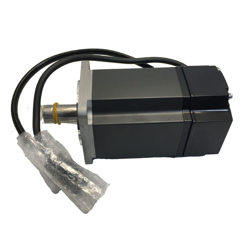
Mitsubishi Electric HC-KFE73BK AC Servo Motor
750W | 2.4 Nm Rated | 3000 RPM | Non-Excitation Electromagnetic Brake | Keyway Shaft | 80×80mm Flange | MR-E-70A Compatible | IP55 Body | Discontinued
The Largest Motor in the HC-KFE Family — With All the Safety Features
Step up from the 400W class to 750W within the MELSERVO MR-E ecosystem and you land at the HC-KFE73BK: the top of the HC-KFE series range, combining the highest output wattage the MR-E amplifier platform supports with both a built-in electromagnetic brake for power-off position security and a keyed shaft for reliable positive torque transmission. It is the fully-optioned variant in its series tier — brake, keyway, and maximum rated power in a single motor assembly.
The HC-KFE73BK occupies a specific and well-defined application niche: general-purpose servo axes that demand more continuous torque and mechanical output than the 400W class can deliver, while keeping the drive system on the economical, pulse-command-based MR-E amplifier rather than stepping up to MR-J2S or MR-J3 platforms. The 24VDC spring-applied brake ensures the axis holds firm when the servo is de-energized — a requirement that the standard HC-KFE73 without brake cannot meet.
Technical Specifications
| Parameter |
Value |
| Part Number |
HC-KFE73BK |
| Series |
MELSERVO HC-KFE (MR-E compatible) |
| Rated Output Power |
750W (0.75 kW) |
| Rated Torque |
2.4 Nm |
| Peak Torque (Maximum) |
7.2 Nm |
| Peak-to-Rated Torque Ratio |
3:1 |
| Rated Speed |
3,000 RPM |
| Maximum Speed |
4,500 RPM |
| Encoder Type |
Incremental |
| Encoder Resolution |
10,000 pulses/rev |
| Supply Voltage |
200V AC class (3-phase) |
| Flange Size |
80 × 80 mm |
| Shaft Type |
Straight with keyway (key included) |
| Protection Rating |
IP55 (motor body) |
| IP Rating Exception |
Shaft-through portion and connectors NOT IP55 |
| Electromagnetic Brake Type |
Non-excitation activation (spring-applied, fail-safe) |
| Brake Activation Voltage |
DC 24V |
| Brake Power Supply |
Separate 24VDC — must not share with interface I/O supply |
| Brake Engaged State |
When 24VDC is OFF |
| Brake Released State |
When 24VDC is ON |
| Compatible Servo Amplifier |
MR-E-70A / MR-E-70AG |
| Operating Temperature |
0°C to +40°C |
| Storage Temperature |
−15°C to +70°C |
| Ambient Humidity |
Max 80% RH (non-condensing) |
| Maximum Altitude |
1,000 m above sea level |
| Vibration Resistance (X/Y) |
49 m/s² |
| Insulation Class |
130 (B) |
| Structure |
Totally enclosed, natural cooling |
| Country of Origin |
Japan |
| Product Status |
Discontinued |
Three Distinguishing Features — What BK Actually Delivers
The HC-KFE73BK part number encodes three meaningful decisions that each have direct engineering consequences for the application.
The 73 — 750W output at the MR-E ceiling. The HC-KFE family runs from 100W (HC-KFE13) through 200W, 400W, and up to 750W. The 73 designator places this motor at the ceiling of what the MR-E amplifier can drive. Paired with the MR-E-70A, the system delivers 2.4 Nm continuously — nearly double the 1.3 Nm available from the 400W HC-KFE43B. For axes where the 400W motor ran close to rated current in normal operation, or where load torque analysis indicated insufficient margin, the 750W class is the natural next step without changing the amplifier platform architecture.
The B — non-excitation electromagnetic brake. A spring-applied brake is integrated into the rear of the motor housing. When 24VDC is removed — whether by a controlled shutdown, an emergency stop, or a power interruption — the spring engages the brake immediately, locking the shaft without requiring any signal from the controller. This fail-safe principle is the defining feature that differentiates the HC-KFE73BK from the standard HC-KFE73K. No power, no controller signal, no external relay action is needed for the brake to engage.
The K — keyway shaft. At 750W, positive coupling is not optional for most applications. A keyway provides a mechanical interlock between the shaft and the driven component — whether a coupling hub, pulley, or gear — that prevents relative rotation between the two regardless of whether the interference fit is maintained over time and temperature cycling. The motor ships with the key. The keyway dimension follows JIS standards appropriate to the 750W shaft size.
The 80×80mm Flange: A Step Up from the 400W Class
The HC-KFE73BK mounts on an 80×80mm square flange — a full step larger than the 60×60mm flange of the 400W HC-KFE43BK. This size step has a direct implication for installations being upgraded: machines designed around the smaller 60×60mm flange class cannot accept the 80×80mm motor without modifications to the motor mounting plate. The bolt hole pattern and flange register diameter change at this size boundary.
Within the 80×80mm class, however, the HC-KFE73BK shares its flange footprint with the HC-KFS73BK (the MR-J2S equivalent) and with current-generation 750W motors like the HG-KR73BK. This means that a machine mounting plate designed for any 80×80mm MELSERVO 750W motor is mechanically compatible with the HC-KFE73BK. Shaft protrusion length and body axial dimensions must still be checked against the specific application, particularly for the brake variant given its extended rear housing, but the flange face remains the consistent reference.
Torque Headroom: What the 7.2 Nm Peak Means in Practice
The HC-KFE73BK's 2.4 Nm rated torque is the number against which continuous load sizing is performed. The 7.2 Nm peak — three times rated — is available for the transient demands of acceleration phases and brief overload conditions during cutting or clamping operations.
That 4.8 Nm difference between rated and peak is the axis's acceleration reserve. On a horizontal ballscrew axis with typical load inertia ratios, the full 7.2 Nm peak torque translates to acceleration rates that reduce point-to-point move times significantly compared to operating the axis at rated torque only. Whether the amplifier's electronic current limit will sustain the peak current needed to produce 7.2 Nm continuously through the whole acceleration phase depends on the load-to-motor inertia ratio and the duty cycle — the MR-E-70A's built-in electronic thermal protection monitors cumulative heating and enforces protection limits accordingly.
For vertical axes where load torque is always present, the 2.4 Nm rated figure covers the gravity component, and the remaining margin goes to dynamics. The 70% rated torque rule for unbalanced torque applications — stated in Mitsubishi's MR-E documentation — means gravity loads on the shaft should not exceed 1.68 Nm in a properly sized vertical axis design.
Brake Integration in Machine Design
Adding a brake motor to a machine design involves more than swapping the motor variant. The HC-KFE73BK requires two specific design considerations that do not apply to the standard HC-KFE73K.
First, the 24VDC brake supply circuit. Per Mitsubishi's MR-E manual, the brake's 24VDC supply must be a dedicated circuit — not shared with the 24VDC used for the amplifier's digital I/O signals. The 6-pin motor power connector on the HC-KFE73BK (compared to the 4-pin connector on the standard variant) carries both the three-phase motor power leads and the two brake supply wires. A separate contactor or relay circuit, driven by the MR-E amplifier's MBR (electromagnetic brake interlock) output signal, controls the 24VDC to the brake coil.
Second, the MBR signal and Parameter No. 1. The MR-E amplifier's electromagnetic brake interlock output must be enabled via parameter setting. This output coordinates the timing between servo-on/off transitions and brake engagement, preventing the brake from snapping onto a rotating shaft and protecting both the brake lining life and the mechanical drive components. For vertical axes specifically, Mitsubishi's documentation calls out the MBR signal as a required configuration element — the controlled brake timing prevents load drop during the axis stop sequence.
Positioning the HC-KFE73BK Within Its Generation
The HC-KFE series and the MR-E amplifier represent a product generation that delivered capable, cost-effective general-purpose servo control during the period when absolute encoder systems and digital bus interfaces were premium options rather than mainstream features. The HC-KFE73BK was the appropriate selection when the application required 750W output and brake functionality but did not justify the absolute encoder and higher-cost amplifier of the HC-KFS/MR-J2S tier.
Both the motor and the MR-E amplifier are now discontinued. Available supply comes from aftermarket inventory, surplus stock, and removed-from-service units. For new machine designs, Mitsubishi's documented migration path leads to the MR-JE or MR-J4 series amplifiers with current-generation HG series motors — the HG-KR73BK being the approximate functional successor in the 750W brake + keyway class, with the same 80×80mm flange footprint but a 22-bit absolute encoder and the current MELSERVO J4 interface.
Frequently Asked Questions
Q1: What is the MR-E amplifier model that matches the HC-KFE73BK, and what control modes does it support?
The HC-KFE73BK pairs with the MR-E-70A (pulse train input, position control mode) or the MR-E-70AG (analog speed command input, speed control mode). The "70" in the amplifier designation corresponds to the 750W motor class. The MR-E-70A accepts pulse + direction or quadrature pulse train commands from external positioning controllers, MELSEC PLC positioning modules, or CNC outputs. The MR-E-70AG enables analog speed command integration for applications where the upper-level controller outputs a ±10V analog signal for speed reference. Both amplifier variants support the HC-KFE73BK's electromagnetic brake through the MBR interlock output.
Q2: Why does the 80×80mm HC-KFE73BK use a larger flange than the 60×60mm HC-KFE43BK, and can the same machine mounting plate accept both?
The flange size increases at the 750W class because the motor frame diameter grows to accommodate the larger stator, winding, and rotor assembly needed for higher torque output. The 60×60mm flange of the 400W class and the 80×80mm flange of the 750W class have different bolt hole patterns and flange register diameters — they are not interchangeable. A machine mounting plate designed for a 400W HC-KFE43BK cannot directly accept the HC-KFE73BK without machining or replacing the plate. If a machine originally designed around the 400W motor is being upgraded to 750W, mechanical modifications at the motor mount are part of the work scope.
Q3: The product listing notes the shaft-through portion is not IP55. What does this mean for machine installation?
The HC-KFE series motors carry an IP55 body rating covering the motor housing surface, but Mitsubishi's documentation explicitly states that the shaft-through portion — where the shaft exits the front bearing housing — and the electrical connectors are not protected to IP55. In environments with coolant mist, wash-down water, or airborne fluid contamination, these unprotected points are the motor's vulnerability. Practical mitigation options include positioning the motor in a protected location within the machine enclosure, fitting a shaft seal cover if the machine design permits, or specifying a motor with an oil seal (available in other HC series variants) for wet environments. The connector end also warrants protection, particularly for the encoder connector, since contamination on encoder signal pins is a common cause of position feedback errors.
Q4: Does the electromagnetic brake on the HC-KFE73BK hold 2.4 Nm — the full rated motor torque?
Mitsubishi's design approach for the HC-KFE brake variants matches the brake's static friction torque to the motor's rated output torque. For the 750W class, the brake is rated to hold the shaft against a torque load corresponding to the motor's 2.4 Nm rated figure. This means the brake can hold a stationary load within normal operating torque without slipping, which is the intended use case. The brake is not designed for dynamic stopping of a rotating shaft at rated speed — doing so rapidly depletes the brake's wear life and can cause mechanical shock in the drive train. Correct practice is to bring the motor to a controlled stop via the servo amplifier before the brake engages to hold the stopped position.
Q5: Is the HC-KFE73BK interchangeable with the HC-KFS73BK from a system integration perspective?
The two motors share an 80×80mm flange mounting footprint, making mechanical substitution straightforward. However, they are not system-interchangeable without changing the servo amplifier. The HC-KFE73BK uses an incremental 10,000 ppr encoder and pairs with the MR-E-70A, while the HC-KFS73BK carries a 17-bit absolute encoder (131,072 ppr) and pairs with the MR-J2S-70A/B/CP/CL amplifiers. The encoder connectors, signal protocols, and amplifier interfaces are entirely different. Replacing one with the other requires a matched amplifier change and reconfiguration of the drive axis. The HC-KFE73BK → HC-KFS73BK direction is an upgrade (higher encoder resolution, absolute position retention, no homing required), while the reverse is a downgrade that would rarely be specified intentionally.

 Your message must be between 20-3,000 characters!