Mitsubishi Electric HC-KFE43B AC Servo Motor with Electromagnetic Brake
400W | 1.3 Nm Rated | 3000 RPM | Non-Excitation Electromagnetic Brake | 24VDC | Keyway Shaft | 60×60mm Flange | MR-E-40A Compatible | IP55 Body | Discontinued
When Power-Off Position Holding Is Not Optional
Every servo axis stops. The question that separates a general-purpose servo motor from a brake-equipped one is what happens at that moment: does the axis hold its position under load, or does it coast, drift, or fall? For vertical axes carrying tooling, clamping systems that must grip across a power interruption, or any driven mechanism where an uncontrolled de-energized position is a hazard, the answer determines which motor gets specified.
The Mitsubishi Electric HC-KFE43B is the electromagnetic brake variant of the HC-KFE43 — a 400W, 3000 RPM motor from the MELSERVO MR-E series platform with a spring-applied, non-excitation electromagnetic brake built directly into the rear of the motor housing. The motor and brake are a single integrated assembly. There is no separate brake mounted externally, no additional mounting hardware to source, and no alignment between motor and brake to maintain over the machine's service life.
The "B" suffix in the Mitsubishi designation is consistent across the HC and HF motor series: it always indicates a motor with electromagnetic brake, applied to an otherwise identical base motor. Mechanically and electrically, the HC-KFE43B is the HC-KFE43 with one additional subsystem whose significance — in the right application — is considerable.
Technical Specifications
| Parameter |
Value |
| Part Number |
HC-KFE43B |
| Series |
MELSERVO HC-KFE (MR-E compatible) |
| Rated Output Power |
400W (0.4 kW) |
| Rated Torque |
1.3 Nm |
| Peak Torque (Maximum) |
3.8 Nm |
| Rated Speed |
3,000 RPM |
| Maximum Speed |
4,500 RPM |
| Encoder Type |
Incremental |
| Encoder Resolution |
10,000 pulses/rev (effective) |
| Supply Voltage |
200V AC class |
| Flange Size |
60 × 60 mm |
| Shaft Type |
Straight with keyway (key included) |
| Protection Rating |
IP55 (motor body) |
| IP Rating Exception |
Shaft-through portion and connectors NOT IP55 |
| Electromagnetic Brake Type |
Non-excitation activation (spring-applied / fail-safe) |
| Brake Activation Voltage |
DC 24V |
| Brake Power Supply |
Separate 24VDC required (must NOT share with interface power) |
| Brake State when 24VDC OFF |
Engaged (locked) |
| Brake State when 24VDC ON |
Released (motor free to rotate) |
| Compatible Servo Amplifier |
MR-E-40A / MR-E-40AG |
| Operating Temperature |
0°C to +40°C |
| Storage Temperature |
−15°C to +70°C |
| Ambient Humidity |
Max 80% RH (non-condensing) |
| Maximum Altitude |
1,000 m above sea level |
| Vibration Resistance (X/Y) |
49 m/s² |
| Insulation Class |
130 (B) |
| Country of Origin |
Japan |
| Product Status |
Discontinued |
The Non-Excitation Brake: Fail-Safe by Design
The phrase "non-excitation activation" appears in every Mitsubishi brake motor specification and means something specific: the brake engages by spring force when power is removed, and releases when 24VDC is applied. This is the opposite of an excitation-type brake, which holds only while powered.
The practical consequence matters enormously in safety-critical applications. When the machine power supply is interrupted — whether through a controlled shutdown sequence, an emergency stop, or an unplanned power failure — the brake on the HC-KFE43B engages automatically. No signal, no controller action, and no backup power is needed for the brake to hold the motor shaft. The default state of the brake is locked.
This fail-safe characteristic is why spring-applied non-excitation brakes are the standard specification for vertical axes, clamping mechanisms, and any axis where an uncontrolled movement with power removed represents a hazard. The HC-KFE43B's brake holds the shaft against gravity and against any external torque load up to the brake's static friction torque — rated to match the motor's 1.3 Nm rated torque value in this motor class, as is standard in Mitsubishi's matched motor-brake design practice.
Brake Power Supply: A Dedicated 24VDC Circuit Is Required
The MR-E series documentation is explicit on this point: the 24VDC supply to the electromagnetic brake must not be shared with the 24VDC interface power supply used for the amplifier's digital I/O signals. The two circuits must remain separate. Sharing the supply introduces the risk of a voltage drop on the brake circuit when I/O signals switch, which can cause incomplete brake release or unintended brake engagement during motor operation — neither of which is acceptable in a functioning servo axis.
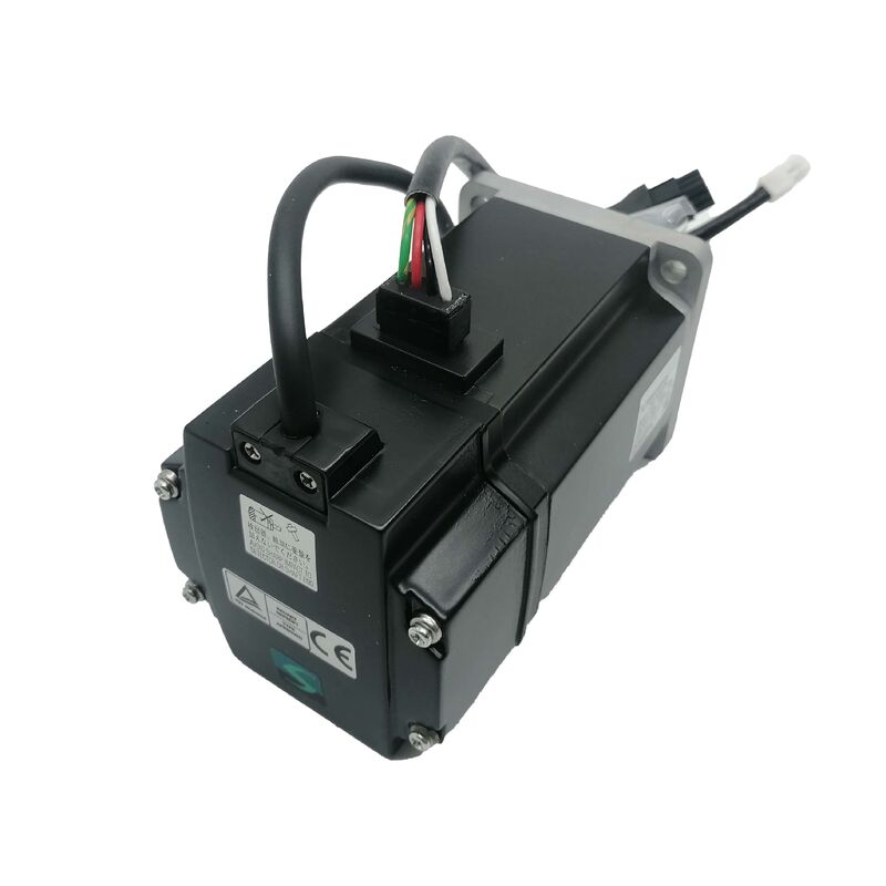
In practice, this means the control panel design for a machine using the HC-KFE43B must include a dedicated 24VDC rail for brake power, sized appropriately for the brake coil's current draw. The motor's power connector accommodates both the three-phase motor leads and the brake supply leads in a single 6-pin connector assembly, compared to the 4-pin connector used on the standard HC-KFE43 without brake. This connector difference is an immediate visual identifier when comparing the two motor variants in a parts context.
Brake Timing and the MBR Signal
The electromagnetic brake interlock signal (MBR) output from the MR-E amplifier coordinates the brake release timing with the servo amplifier's operating state. Before the servo motor can run, the MBR signal releases the brake by energizing the 24VDC circuit. When the motor is commanded to stop and the servo-on signal is turned off, the MBR output manages the timing delay between servo off and brake engagement — preventing the brake from snapping onto a still-rotating shaft, which would accelerate brake lining wear and produce mechanical shock loads.
Mitsubishi's MR-E Instruction Manual covers the required parameter settings for the brake interlock function. Specifically, Parameter No. 1 must be set to enable the MBR signal output, and Parameter No. 33 (electromagnetic brake sequence output) sets the time delay (Tb) at servo-off before the brake engages. These settings are configured for the specific application's stopping behavior and load characteristics, not left at factory default in a production machine.
For vertical axis applications, the MR-E documentation specifically calls out use of the electromagnetic brake interlock signal (MBR) when the motor controls a vertical shaft — the timing coordination between servo-off and brake engagement is critical to prevent the load from dropping during the axis stop sequence.
Keyway Shaft: Standard on 400W
The HC-KFE43B shaft includes a keyway as standard. In Mitsubishi's HC-KFE lineup, keyways are standard on the 200W and 400W motor sizes — the coupling torque capacity of a plain friction-fit hub on a small shaft is insufficient for reliable torque transmission at these power levels in industrial duty cycles. The key provides positive torque transmission between the motor shaft and the driven coupling or pulley, eliminating the reliance on clamping force alone.
The motor ships with the key included. Coupling selection should account for the standard NEMA 34 mounting adapter option for North American machine installations, though the motor shaft dimensions and keyway are to JIS standard — confirming shaft dimensions against the application coupling bore is always the correct first step before installation.
Body Length Difference from HC-KFE43
Adding the electromagnetic brake section to the rear of the motor housing increases overall body length compared to the HC-KFE43. The brake housing, spring pack, and friction disc assembly extend the motor's axial dimension. For retrofit situations where an HC-KFE43 is being replaced with an HC-KFE43B, or where a brake motor is being added to an existing machine axis, the mounting depth and cable routing clearances behind the motor must be verified against the increased length before mechanical installation begins.
The flange dimensions, bolt hole pattern, and shaft protrusion on the output side are identical between the standard and brake variants — the length difference is entirely at the rear of the motor. If the machine has a rear obstacle clearance dimension that was sized for the standard motor, it may require adjustment to accommodate the brake model.
Application Context
The HC-KFE43B is most commonly found in machine designs where one or more axes require brake functionality while the overall drive system budget favors the MR-E general-purpose amplifier platform over the higher-specification MR-J2S or MR-J3 series. Typical applications include:
- Vertical feed axes on small machining centers or drilling machines — where the tool or spindle head must hold position under gravity when the servo is de-energized
- Clamping and fixturing mechanisms — where a powered clamp position must be maintained through a power interruption without releasing the workpiece
- Rotary indexing tables — where a locked position is required between index moves, using the brake to resist torque at the indexed position rather than maintaining servo torque continuously
- Material handling Z-axes — where a load must be safely suspended during cycle pauses, emergency stops, or maintenance operations
Frequently Asked Questions
Q1: Does the electromagnetic brake on the HC-KFE43B provide rated holding torque equal to the motor's rated output torque?
In Mitsubishi's design practice for the HC-KFE series, the brake's static friction torque is rated to match the motor's rated torque — 1.3 Nm for the 400W class. This means the brake is designed to hold a load at the motor shaft level that corresponds to the motor's rated output under normal operating conditions. It is important to note that the brake is specified for holding stationary loads, not for decelerating a rotating shaft. Using it as a dynamic stopping brake — commanding the brake to engage while the motor is still turning at speed — will rapidly wear the brake lining and shorten its service life significantly. The correct sequence is to bring the motor to a stop through the servo control system first, then engage the brake to hold the stopped position.
Q2: Can the 24VDC power supply for the brake be taken from the same 24VDC rail that powers the MR-E amplifier's interface I/O?
No. Mitsubishi's MR-E series documentation explicitly prohibits sharing the 24VDC interface power supply between the I/O interface circuits and the electromagnetic brake. The brake must have a dedicated 24VDC power supply. The reason is straightforward: I/O switching events cause current transients on the 24VDC rail, which can cause momentary voltage drops that partially or fully activate the brake during motor operation, causing mechanical shock and premature brake wear. A dedicated brake supply isolates these circuits and ensures the brake operates reliably under all I/O switching conditions.
Q3: What happens to brake operation if the amplifier develops a fault and cuts power?
This is the scenario the non-excitation brake design is specifically intended to address. When the MR-E amplifier shuts down — whether due to an alarm, an emergency stop signal, or a loss of main power — the 24VDC to the brake coil is also cut (either by the alarm output circuit or by the power failure itself). The spring-applied brake immediately engages, locking the motor shaft without requiring any signal from the controller. This automatic engagement is independent of the amplifier's operating state. For vertical axes or clamping applications, this is the fundamental safety behavior that makes the non-excitation brake the industry-standard selection for hazard-prevention applications.
Q4: What is the motor body length difference between the HC-KFE43 and the HC-KFE43B, and does the flange mounting remain the same?
The flange mounting dimensions — the 60×60mm square flange, bolt hole pattern, and shaft protrusion length on the output end — are identical between the HC-KFE43 and HC-KFE43B. The only dimensional change is increased overall body length due to the brake module added at the motor's rear. Mitsubishi's outline drawing documentation (section 14.8.1 of the MR-E manual) shows the specific body lengths for each variant, and these should be consulted when designing or verifying rear clearance behind the motor in the machine structure. For replacement of an existing standard motor with a brake model in a retrofit, verify rear clearance before ordering.
Q5: Is the HC-KFE43B a suitable direct replacement for the HC-KFS43B (the MR-J2S brake motor) in an existing machine?
Mechanically, the 60×60mm flange footprint is shared between the HC-KFE43B and HC-KFS43B, making the mounting plate compatible. However, the encoder and amplifier interfaces are entirely different. The HC-KFE43B uses an incremental encoder paired with the MR-E amplifier, while the HC-KFS43B uses a 17-bit absolute encoder (131,072 ppr) paired with the MR-J2S amplifier. The encoder connector types, signal protocols, and cable assemblies are not interchangeable. A swap from HC-KFS43B to HC-KFE43B would require replacing the amplifier to MR-E and reconfiguring the entire drive axis for incremental encoder operation with homing cycles — a significant system change. The reverse direction (upgrading from HC-KFE43B to HC-KFS43B or a current-generation HG series motor with brake) is the more common migration path when a machine system is being upgraded.

 Your message must be between 20-3,000 characters!