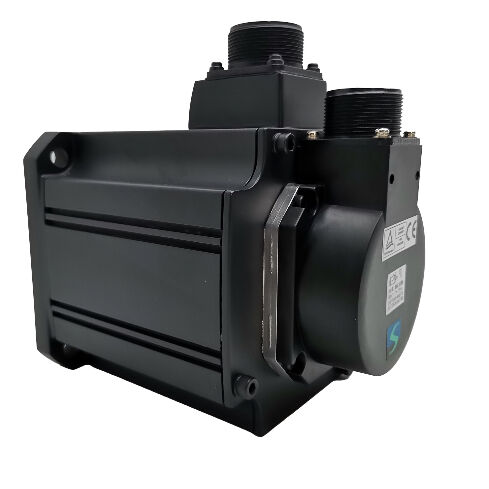
Mitsubishi HC-SFS103B (HCSFS103B) — 1kW AC Servo Motor with Electromagnetic Brake, Straight Shaft, 3000 rpm, MELSERVO J2-Super Series
Product Overview
Part Number: HC-SFS103B
Also Searched As: HCSFS103B, HC SFS 103B, HC-SFS-103B
Series: Mitsubishi MELSERVO HC-SFS (J2-Super Generation)
Classification: Medium-Inertia AC Brushless Servo Motor — 1 kW, 200V class, 3000 rpm, Straight Shaft, Spring-Applied Electromagnetic Brake
What the "B" Changes — and Why It Matters
The Mitsubishi HC-SFS103B shares every specification with the HC-SFS103 except one: a spring-applied electromagnetic brake integrated into the rear of the motor housing. Same 1kW output. Same 3.18 Nm rated torque and 9.55 Nm peak. Same 17-bit absolute encoder at 131,072 ppr. Same 130 × 130 mm flange on IP65-rated frame. Same MR-J2S-100 amplifier. One additional component — and that component is what makes this motor the correct choice for a specific class of axis that the no-brake variant cannot safely serve.
The brake is spring-applied and electrically released. The spring holds the friction disc against the braking surface by default. Applying 24V DC to the brake coil creates the magnetic force that lifts the disc and frees the shaft. Remove that voltage — for any reason, planned or not — and the spring immediately re-engages. E-stop removes panel power: brake applies. Amplifier fault trips the main contactor: brake applies. End-of-shift servo-off sequence: brake applies. Unplanned mains interruption at any moment during the working day: brake applies.
No software. No PLC sequence. No amplifier being functional. The axis holds mechanically, passively, immediately, every time.
For a 1kW servo motor driving a vertical or inclined axis where the load has a gravitational component that would cause movement at servo-off, this is the functional requirement the spring-applied brake meets. The HC-SFS103B is built for exactly that application.
Technical Specifications
| Parameter |
Value |
| Part Number |
HC-SFS103B |
| Rated Output |
1,000 W (1 kW) |
| Supply Voltage |
200V class (3-phase 200–230V AC) |
| Rated Speed |
3,000 rpm |
| Maximum Speed |
4,500 rpm |
| Rated Torque |
3.18 Nm |
| Peak Torque |
9.55 Nm |
| Encoder Type |
17-bit serial absolute |
| Encoder Resolution |
131,072 ppr |
| Shaft Type |
Straight (no keyway) |
| Electromagnetic Brake |
Spring-applied, electrically released (24V DC) |
| Flange Size |
130 × 130 mm |
| Protection Rating |
IP65 |
| Oil Seal |
Fitted |
| Inertia Class |
Medium inertia |
| Ambient Temperature (Operation) |
0°C to +40°C |
| Storage Temperature |
−15°C to +70°C |
| Compatible Amplifiers |
MR-J2S-100A / MR-J2S-100B / MR-J2S-100CP |
| Series Generation |
MELSERVO J2-Super |
| Status |
Discontinued — available as stock |
The Brake Mechanism: Fail-Safe by Design
There are two fundamentally different brake design philosophies used on servo motors, and the distinction is not academic — it defines the motor's behaviour under every failure mode the machine might encounter.
An electrically applied brake engages only when coil current is supplied. Remove power and the brake releases. This design is useful for controlled clamping during operation, but it provides no protection when power is lost. A power failure on a machine with electrically applied brakes on its vertical axes produces uncontrolled axis movement — exactly the scenario the brake was meant to prevent.
A spring-applied brake — the type fitted to the HC-SFS103B — reverses this logic. The spring holds the brake engaged by default. Electrical energy is required to open it, not to close it. Power loss of any kind causes the spring to close the brake automatically. The axis is held without any active intervention.
This is why the spring-applied design is the standard for servo motor holding brakes on vertical and gravity-loaded axes in industrial machinery. It is not simply a holding device — it is a fail-safe device. The distinction is important for machine safety assessment and for compliance with machinery safety standards that require positive restraint on axes with gravitational load components.
At 1kW on a compact 130 × 130 mm frame, the HC-SFS103B brings this fail-safe characteristic to the smaller end of the servo motor range — vertical Z-axes on compact machining centres and drilling machines, vertical robot joint drives, inclined feed mechanisms, lift stations on small assembly and handling equipment. These axes exist across a wide variety of machines, and the compact frame of the HC-SFS103B means it fits the space constraints that these lighter-duty vertical axes typically impose.
3.18 Nm at 3000 rpm: Light Load, High Speed, Precise Position
Three point one eight Newton-metres of continuous torque at 3,000 rpm characterises a specific category of axis. It is not a high-torque axis — 3.18 Nm continuous is a relatively modest sustained force. But it is a fast and precise axis, with 131,072 encoder counts per revolution monitoring shaft angle and 9.55 Nm peak torque available for acceleration transients.
For the vertical and inclined axes this motor typically serves, load masses are generally modest. A drilling head Z-axis on a compact machining centre carries the spindle motor, quill, and toolholder — perhaps 15–25 kg of moving mass for smaller machines. An elbow joint on a lightweight robot arm. A vertical tool changer shuttle in a compact tool magazine. A small part lift on an assembly machine. These mechanisms need accurate position control, reliable braking at rest, and compact motor packaging — not the high sustained torques of large machining centre Z-axes or heavy industrial lift mechanisms.
The 3,000 rpm rated speed matters for these applications in a specific way. Many small vertical servo axes use a ball screw for the linear-to-rotary conversion. At 3,000 rpm with a 5mm pitch screw, the axis moves at 15 m/min during rapid traverse — genuinely fast for a compact machining centre Z-axis. The absolute encoder at 131,072 ppr gives the position loop the resolution to command fine incremental moves and maintain accurate positioning throughout that speed range.
The maximum speed of 4,500 rpm extends the operating range above rated speed in the constant-power region, where available torque decreases proportionally. This extended range is useful for rapid positioning phases on light-load axes where the traversal torque demand is well below rated and maximum speed is desirable for minimising cycle time.
Absolute Encoder, Braked Axis, and the Restart Advantage
The combination of a spring-applied brake and a 17-bit serial absolute encoder on the HC-SFS103B creates an operational characteristic that matters significantly for production machines with vertical axes.
Consider what happens when a vertical axis stops unexpectedly — an E-stop during a machining cycle, a power interruption at any point in a positioning move, a panel fault during automated operation. On a machine with a spring-applied brake and absolute encoder: the brake engages immediately and holds the axis mechanically. The encoder retains the exact shaft angle in memory, backed by the A6BAT battery in the MR-J2S-100 amplifier throughout the outage. When power returns, the amplifier reads the absolute position immediately. The controller knows exactly where the axis is. Servo lock is established. The brake releases in the correct sequence. The machine is ready to resume — from whatever position the axis stopped, without any movement to find a reference.
The alternative — an incremental encoder with a spring-applied brake — holds the axis mechanically but provides no position information after power loss. On restart, the axis must execute a homing routine to find its reference position before production can resume. On a small machining centre Z-axis where the homing movement takes the spindle toward the table, that homing routine requires clearing the work area, which adds time and manual intervention to every unexpected stop.
The absolute encoder eliminates this entirely. The brake holds the axis safely; the encoder remembers where it is. Restart is immediate and fully automated.
Battery maintenance. The A6BAT in the MR-J2S-100 amplifier maintains the multi-turn counter through power-off periods. Replace it at the first low-battery alarm — not at the next scheduled maintenance stop, and not after the next convenient moment. A depleted battery resets the counter. On a braked vertical axis, that reset means a homing routine on the next startup, which on many machines requires human intervention to make safe. The alarm is the notification that the battery replacement window is open; acting on it promptly is the practice that keeps production running without interruption.
Brake Wiring and Sequencing at 1kW
The brake coil on the HC-SFS103B requires a dedicated 24V DC circuit in the machine panel — separate from the servo amplifier's power supply and output terminals. Panel design for this motor includes a 24V DC supply sized for the brake coil current, a relay with contacts rated for the coil load and with appropriate surge suppression across the coil terminals, and interlock logic that sequences brake release and engagement correctly relative to the amplifier's servo enable state.
On release — opening the brake: The servo must be enabled and servo lock established before the brake coil is energised and the brake releases. On a vertical axis at 1kW, the load mass is modest compared to heavier motors, but the principle is the same: if the brake releases before the amplifier is holding position, the axis moves under gravity until the servo catches up. At small mass and short travel, this slip may be minor. At larger loads or longer travel, it can cause a position error alarm or, worse, mechanical contact. The MBR (Magnetic Brake Release) output on the MR-J2S-100 manages this sequence automatically when wired to the brake relay — the amplifier signals when servo lock is confirmed and the brake can safely release.
On engagement — closing the brake: Bring the axis to rest under servo control before engaging the brake. The correct three-step sequence: decelerate to zero under servo, engage brake, then remove servo enable. Applying the brake to a moving shaft generates heat and wear in the friction disc. On a 1kW motor with frequent start-stop cycles — an assembly machine Z-axis completing hundreds of moves per shift — following this sequence consistently makes a measurable difference to brake service life over years of operation.
Surge suppression. The brake coil is an inductive load. When the relay opens and cuts current to the coil, the collapsing magnetic field produces a voltage spike. A flyback diode across a DC coil — the standard solution for 24V DC brake circuits — is mandatory. Omitting it exposes relay contacts to repeated arc damage and potentially couples noise into adjacent control electronics. This is standard industrial panel practice for any inductive coil; the brake coil on the HC-SFS103B is no exception.
When the HC-SFS103B Is Right — and When It Isn't
The spring-applied brake adds weight, length, and panel circuit complexity compared to the no-brake HC-SFS103. On horizontal axes where servo lock alone holds position adequately, this additional complexity delivers no functional benefit. On those axes, the HC-SFS103 is the better choice.
The HC-SFS103B is the right motor when:
The axis is vertical or inclined, and the load would move downward under gravity if servo current dropped to zero. The spring-applied brake holds the load mechanically regardless of servo state.
Machine safety requirements mandate positive mechanical restraint on gravity-loaded axes. For CE-marked machinery under European machinery directives, the requirement for positive restraint on vertical axes is typically explicit in the safety assessment. A spring-applied brake satisfies this requirement; servo lock does not.
Restart after unexpected stops must be fast and fully automated. The combination of spring-applied brake and absolute encoder means the axis holds position through any power interruption and reports its exact position on restart. No homing movement, no manual clearance, no human intervention required.
The axis carries a load that should not slip if electrical supply is interrupted. In semiconductor handling, precision measurement, and medical equipment applications, axis position at any moment — including during a power fault — must be maintained. The spring-applied brake makes this unconditional.
Where none of these conditions apply — confirmed horizontal or balanced axis, no gravitational load component, no regulatory requirement for positive restraint — the HC-SFS103 without a brake is the cleaner specification. Installing the HC-SFS103B on every axis regardless of whether the brake is needed adds cost, panel circuit complexity, and maintenance items that produce no functional return on those axes.
Compatible Amplifiers
The HC-SFS103B pairs with the MR-J2S-100 amplifier family — the 1kW capacity J2-Super platform. Three interface variants:
MR-J2S-100A handles analog and pulse-train commands from CNC systems, PLCs, and external motion controllers. Position, speed, and torque control modes are all available, along with switched-mode combinations P/S, S/T, and T/P. RS-232C connects to MR Configurator for commissioning, parameter setting, and diagnostic monitoring. For machine tool auxiliary axes, standalone positioning axes, and any application where the command source is an external controller, this is the standard choice.
MR-J2S-100B connects to Mitsubishi A-series and Q-series motion controllers via SSCNET fiber-optic serial bus. Axis commands and all feedback data travel over the fiber network. For multi-axis machines where the vertical axis must coordinate with horizontal axes under a motion controller — a Z-axis on a CNC system with simultaneous X, Y, Z motion — the SSCNET bus provides the real-time axis coupling that pulse and analog interfaces cannot deliver.
MR-J2S-100CP provides built-in single-axis positioning with up to 31 stored point-table positions, activated by digital I/O or CC-Link command. For standalone vertical positioning axes — drill head Z-feeds, simple lift stations, indexed vertical transfer slides — that do not require coordination with other axes, the CP eliminates the cost and complexity of a dedicated motion controller.
All three variants include the MBR (Magnetic Brake Release) output for brake relay sequencing, real-time auto-tuning, adaptive vibration suppression, and the full J2-Super protective function suite including electronic thermal overload, overspeed, encoder fault detection, and regenerative overvoltage protection.
Compatibility notes. The HC-SFS103B requires an MR-J2S-100 amplifier. It is not compatible with first-generation MR-J2-100 amplifiers, which cannot decode the 17-bit J2-Super encoder serial protocol. For machines on original MR-J2-100 hardware, the HC-SF103B (same mechanical specification, 14-bit encoder, spring-applied brake) is the correct motor. Not compatible with MR-J3 or MR-J4 amplifiers without a renewal adapter kit.
HC-SFS 3000 rpm Braked Family: The 103B in Context
| Model |
Output |
Rated Torque |
Peak Torque |
Flange |
Amplifier |
| HC-SFS53B |
500 W |
1.59 Nm |
4.77 Nm |
130 × 130 mm |
MR-J2S-60 |
| HC-SFS103B |
1,000 W |
3.18 Nm |
9.55 Nm |
130 × 130 mm |
MR-J2S-100 |
| HC-SFS153B |
1,500 W |
4.78 Nm |
14.3 Nm |
130 × 130 mm |
MR-J2S-200 |
| HC-SFS203B |
2,000 W |
6.37 Nm |
19.1 Nm |
130 × 130 mm |
MR-J2S-200 |
| HC-SFS353B |
3,500 W |
11.1 Nm |
33.3 Nm |
176 × 176 mm |
MR-J2S-350 |
The HC-SFS103B sits at the second step in the 3000 rpm braked family, above the 500W HC-SFS53B and below the 1.5kW HC-SFS153B. All four compact-frame models share the 130 × 130 mm mounting interface — a machine designed for one accommodates any of the others without mechanical modification. The amplifier class changes between the HC-SFS103B (MR-J2S-100) and the HC-SFS153B/203B (MR-J2S-200), so capacity upgrades within this group require an amplifier change alongside the motor.
Every capacity in the HC-SFS 3000 rpm range is available in the four standard shaft-and-brake configurations: straight shaft (HC-SFS103), straight shaft with brake (HC-SFS103B), keyed shaft (HC-SFS103K), and keyed shaft with brake (HC-SFS103BK). All four use the MR-J2S-100 amplifier at the 1kW capacity level.
Typical Applications
Vertical Z-axis on compact CNC drilling and machining centres. Drilling head feeds, small vertical spindle Z-axes, and drill cycle actuators on small CNC machines where the spindle assembly mass requires positive mechanical holding at servo-off. The 3,000 rpm rating allows direct ball-screw coupling at practical Z-axis speeds; the spring-applied brake holds the spindle head mechanically during tool changes, E-stops, and end-of-shift shutdowns.
Vertical robot joint drives. Shoulder and elbow joint axes on small industrial robots, SCARA robot arm vertical axes, and delta robot vertical components where the joint carries a gravitational load component and positive mechanical restraint is required for safety. The compact 130 × 130 mm frame fits the tight packaging constraints of robot arm structures; the spring-applied brake provides the fail-safe holding required by industrial robot safety standards.
Vertical transfer and lift stations on assembly equipment. Part lift mechanisms, vertical transfer slides, and indexing lift stations on assembly and test equipment where parts are raised and lowered repeatedly and must be held at intermediate heights while assembly operations complete. The absolute encoder maintains position knowledge through any interruption; the brake holds the lift mechanically at every station.
Inclined axis drives on material handling and forming equipment. Inclined conveyor feeds, angular slide axes on forming machines, and tilted transfer mechanisms where the axis weight component creates a sustained gravitational torque demand requiring positive holding at rest. The spring-applied brake holds the inclined axis at any position in the stroke without servo current.
Tool changer and magazine drives with vertical elements. Vertical tool magazine lift mechanisms, tool changer arm vertical components, and drum-type tool magazine vertical indexing drives on CNC machining centres where the tool magazine or changer mechanism has a vertical travel component requiring brake holding during tool-change dwell and machine stop conditions.
Frequently Asked Questions
Q1: What is the difference between the HC-SFS103B and the HC-SFS103?
Both are 1kW, 3000 rpm, straight-shaft J2-Super motors with identical electrical and dimensional specifications on a 130 × 130 mm flange. The only difference is the brake. The HC-SFS103 has no brake — position at rest is held by amplifier servo lock. The HC-SFS103B has a spring-applied electromagnetic brake that engages mechanically whenever 24V is removed from the brake coil. Use the HC-SFS103B on vertical axes, inclined mechanisms, and any gravity-loaded drive where movement at servo-off would be hazardous or damaging. On confirmed horizontal axes with no gravitational load, the HC-SFS103 is the correct, simpler, and lighter specification.
Q2: Does the spring-applied brake engage automatically during an emergency stop?
Yes — provided the E-stop circuit removes 24V from the brake coil as part of the emergency stop sequence, which is standard panel design practice. When the coil is de-energised for any reason, the spring immediately pushes the brake disc against the friction surface. The engagement is mechanical and instantaneous — it does not depend on the amplifier, the PLC, or any other active system being functional. This is the critical safety advantage of the spring-applied design over electrically applied or friction-only braking.
Q3: Can the HC-SFS103B be used with a first-generation MR-J2-100 amplifier?
No. The HC-SFS103B uses the 17-bit J2-Super encoder serial protocol, which the original MR-J2-100 amplifier cannot read. Connecting the HC-SFS103B to a first-generation MR-J2-100 will produce an encoder communication fault on startup. For machines running MR-J2-100 hardware, the correct braked motor is the HC-SF103B — mechanically identical, 14-bit encoder, spring-applied brake — which is compatible with both MR-J2-100 and MR-J2S-100 amplifiers.
Q4: Where is the absolute encoder backup battery, and what happens if it depletes completely?
The Mitsubishi A6BAT lithium cell is located inside the MR-J2S-100 servo amplifier, not in the motor. It maintains the multi-turn absolute counter through all power-off periods. On a braked vertical axis, this means the brake holds the axis mechanically while the encoder retains the exact shaft angle in memory — so the controller can read the absolute position immediately on restart without any homing movement. If the battery fully depletes, the multi-turn counter resets. On the next startup, the controller will not know the axis position, and a reference-return cycle must be completed before production can resume. Replace the A6BAT at the first low-battery alarm to prevent this.
Q5: The HC-SFS103B is discontinued. Is it still available for machine maintenance?
Yes. The HC-SFS103B remains available through industrial automation surplus dealers and Mitsubishi servo specialist suppliers as new old stock and tested refurbished units, making it a practical sourcing option for maintaining existing J2-Super platform machines. For new machine designs or major platform upgrades, the current-generation braked equivalent draws from the HG-KR or HF-KP series with MR-J4 or MR-JE amplifiers at the equivalent capacity — but both motor and amplifier must be replaced together as the encoder protocols between generations are incompatible.

 Your message must be between 20-3,000 characters!