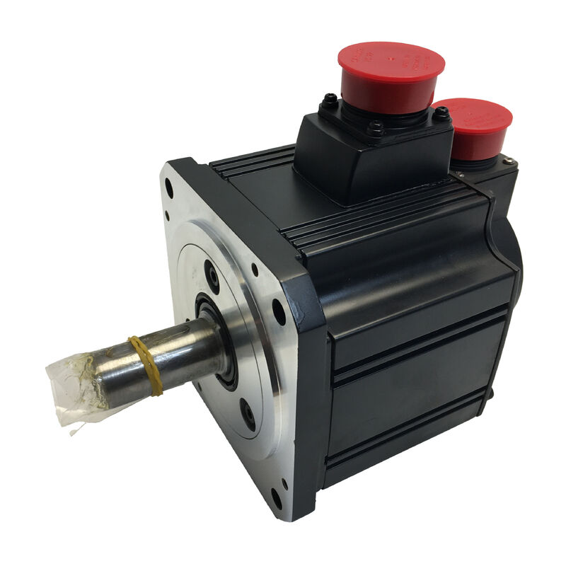
Mitsubishi HC-SFS702B (HCSFS702B) — 7kW AC Servo Motor with Electromagnetic Brake, Straight Shaft, 2000 rpm, MELSERVO J2-Super Series
Product Overview
Part Number: HC-SFS702B
Also Searched As: HCSFS702B, HC SFS 702B, HC-SFS-702B
Series: Mitsubishi MELSERVO HC-SFS (J2-Super Generation)
Classification: Medium-Inertia AC Brushless Servo Motor — 7 kW, 200V class, 2000 rpm, Straight Shaft, Spring-Applied Electromagnetic Brake
What This Motor Is Built For
Seven kilowatts. Thirty-three point four Newton-metres of continuous torque, sustained at 2,000 rpm. One hundred Newton-metres available on demand for acceleration. And behind the shaft, a spring-applied electromagnetic brake that holds the axis mechanically the moment 24V is removed from the coil — whether that removal was planned or not.
The Mitsubishi HC-SFS702B is the 7kW braked member of the HC-SFS 2000 rpm family. It is the motor you specify when the axis is too large for anything smaller, carries a load with a gravitational component that would move without restraint if servo current disappeared, and needs to report its absolute shaft position the instant power returns — without any reference-return movement to find it.
That last point is worth dwelling on. On a large-capacity vertical axis — a heavy spindle head on a gantry machining centre, a palletised workpiece lifted by a servo-driven elevator, a counterbalanced Z-slide on a large portal mill — the combination of a fail-safe brake and an absolute encoder is not a feature upgrade over servo lock and an incremental encoder. It is a fundamentally different level of operational safety and machine uptime. The brake holds the load mechanically at all times when the coil is de-energised. The 17-bit absolute encoder at 131,072 ppr retains the exact shaft angle through any power-off event, backed by the A6BAT battery in the MR-J2S-700 amplifier. When the machine restarts — after an E-stop, after a power interruption, after a shift change — the axis is in a known, safe, mechanically held position, and the controller knows precisely where that position is.
Technical Specifications
| Parameter |
Value |
| Part Number |
HC-SFS702B |
| Rated Output |
7,000 W (7 kW) |
| Supply Voltage |
200V class (3-phase 200–230V AC) |
| Rated Speed |
2,000 rpm |
| Maximum Speed |
3,000 rpm |
| Rated Torque |
33.4 Nm |
| Peak Torque |
100 Nm |
| Encoder Type |
17-bit serial absolute |
| Encoder Resolution |
131,072 ppr |
| Shaft Type |
Straight (no keyway) |
| Electromagnetic Brake |
Spring-applied, electrically released (24V DC) |
| Flange Size |
176 × 176 mm |
| Protection Rating |
IP65 |
| Oil Seal |
Fitted |
| Inertia Class |
Medium inertia |
| Ambient Temperature (Operation) |
0°C to +40°C |
| Storage Temperature |
−15°C to +70°C |
| Vibration Resistance (X axis) |
24.5 m/s² |
| Vibration Resistance (Y axis) |
29.4 m/s² |
| Compatible Amplifiers |
MR-J2S-700A / MR-J2S-700B / MR-J2S-700CP |
| Series Generation |
MELSERVO J2-Super |
| Status |
Discontinued — available as stock |
The Brake Mechanism: Spring-Applied, Electrically Released
Among all the design decisions embedded in the HC-SFS702B, the brake type deserves the most careful attention — because it determines the motor's fail-safe behaviour, and at 7kW on a high-torque vertical axis, fail-safe behaviour is what distinguishes a controlled stop from a dangerous one.
The brake fitted to the HC-SFS702B is spring-applied and electrically released. The spring holds the friction disc against the braking surface by default. Applying 24V DC to the brake coil creates a magnetic field that pulls the disc away from the surface, releasing the shaft for rotation. Remove the 24V — for any reason — and the spring immediately re-engages. There is no intermediate state, no gradual fade, no dependency on servo electronics being functional. The brake applies.
This means: E-stop removes power, brake applies. Panel fault cuts 24V, brake applies. Planned servo-off at end of cycle, brake applies. Unplanned power outage at any moment in the cycle, brake applies. The 7kW axis and whatever mass it is carrying comes to a mechanically held standstill, immediately, without depending on any software, any amplifier function, or any PLC sequence to make it happen.
The contrast with servo lock is stark. Servo lock — the MR-J2S-700's ability to hold axis position by continuously correcting with motor current — requires the amplifier to be powered, the servo to be enabled, and the control system to be functioning normally. Servo lock is reliable under normal operating conditions. It provides no protection when those conditions are not met. For a 7kW axis carrying significant mass with a gravitational load component, that distinction is what the spring-applied brake exists to address.
33.4 Nm Continuous, 100 Nm Peak: Sizing the Axis
Thirty-three point four Newton-metres continuous is the highest sustained torque in the HC-SFS 2000 rpm range. It is a substantial number, and understanding what it means mechanically for the driven mechanism is useful for anyone specifying or replacing this motor.
On a ball-screw axis with a 10mm pitch and 90% screw efficiency, 33.4 Nm of continuous motor torque translates to approximately 18.8 kN of sustained axial force. That covers the heaviest table and workpiece combinations found on large-format CNC machining centres, large gantry mills, and heavy-duty transfer machines. For winding drives running in torque control mode, 33.4 Nm at 2,000 rpm represents a substantial tension-and-speed capability across a wide roll diameter range. For servo-driven press feeds, the sustained feed force during the material advance phase is well within the motor's thermal envelope.
The 100 Nm peak — three times the continuous figure, available for the brief acceleration and deceleration transients of each positioning cycle — is what enables rapid axis movement on heavy-load mechanisms without requiring a larger motor. A positioning cycle that spends 10% of its time accelerating at peak torque, 80% of its time at or below continuous torque, and 10% decelerating stays well within the amplifier's thermal model thresholds. The MR-J2S-700's built-in electronic thermal protection tracks this cumulative loading and alarms predictively before the windings see a damaging temperature.
One design guideline from Mitsubishi's documentation worth noting explicitly for vertical axes: the sustained gravitational torque component — the torque the motor must maintain continuously to hold the load against gravity — should be kept at 70% or below the rated continuous torque. At 33.4 Nm rated, that ceiling is approximately 23.4 Nm. Vertical axis designs approaching or exceeding that figure need either a mechanical counterbalance to reduce the sustained gravitational torque demand, or a motor with a higher continuous torque rating. The brake holds the load mechanically during standstill and removes all sustained torque demand from the motor and amplifier at rest — but during motion, the motor carries the gravitational load, and that load must stay within this guideline for the protection system to function as designed.
Brake Wiring and Sequencing
The brake coil requires a dedicated 24V DC circuit separate from the servo amplifier's power supply. The machine panel must include a 24V DC power supply sized for the brake coil, a brake relay with surge suppression across the coil, and interlock logic that coordinates brake release and engagement with the servo enable sequence.
On release (brake opening): The servo must be enabled before the brake is released. This sequence ensures the amplifier has established servo lock and is actively holding position before the mechanical brake lifts. If the brake releases before servo lock is established, the axis will move under its gravitational load until the amplifier catches up — potentially a significant slip on a heavy vertical axis with no counterbalance. The MBR (Magnetic Brake Release) output signal on the MR-J2S-700 provides a convenient amplifier-managed output for the brake relay, sequenced correctly relative to servo enable. Consult the MR-J2S-700 instruction manual for the specific timing parameters relevant to the axis dynamics.
On engagement (brake closing): Decelerate the axis to rest under servo control, then engage the brake before removing servo enable. Applying the brake to a moving axis — even a slowly moving one — wears the friction surfaces and generates heat within the brake assembly. Allowing the servo to bring the axis to full stop first, then engaging the brake to hold the stopped position, extends brake service life significantly on axes with frequent servo-off cycles.
Surge suppression is mandatory. When the brake coil de-energises, the collapsing magnetic field induces a voltage spike that can damage the relay contacts and affect nearby electronics. A properly rated surge suppressor — diode for DC, varistor or RC network for AC — across the brake coil terminals is not optional. It is part of the installation.
Absolute Encoder and the Vertical Axis Restart Advantage
The 17-bit serial absolute encoder at 131,072 ppr on the HC-SFS702B does everything that J2-Super encoders do: fine angular resolution for high-bandwidth velocity control, multi-turn absolute position backed by the A6BAT battery in the amplifier, and immediate position reporting on power-up without shaft movement.
On a braked vertical axis specifically, the last of those three characteristics carries the most operational weight.
Consider the alternative. An incremental encoder reports position relative to a reference marker that must be found by moving the shaft. On a vertical axis, finding that reference at startup means moving the load — downward or upward — to reach the home position sensor before the controller knows where the axis is. On a machine where the home-position movement could contact a fixture, workpiece, or tooling in the stopped position, that movement introduces risk and requires careful sequencing. On a machine in a production environment where an E-stop might occur at any point in the stroke, the restart procedure after an incremental-encoder axis stop mid-stroke is non-trivial.
With the HC-SFS702B's absolute encoder and the spring-applied brake, the restart procedure is: power the panel, the brake holds the axis mechanically, the encoder reports the exact shaft angle to the amplifier, the controller establishes servo lock, the brake releases in the correct sequence, and the axis is ready — from whatever position it stopped at. No homing movement, no reference-finding, no risk of load contact during restart. The machine goes back into production directly.
Battery maintenance: Replace the A6BAT in the MR-J2S-700 amplifier at the first low-battery alarm. Allowing full battery depletion resets the multi-turn counter, requiring a reference-return cycle. On high-availability production lines, treating a low-battery alarm as an urgent maintenance item — not something to defer until the next scheduled stop — eliminates the unplanned downtime that a counter reset causes.
Compatible Amplifiers
The HC-SFS702B is designed for the MR-J2S-700 amplifier family — the 7kW capacity J2-Super platform. Three interface variants address the main control architectures:
MR-J2S-700A accepts pulse-train position commands and analog speed or torque references from external CNC systems and PLCs. All control modes — position, speed, torque, and switched-mode combinations — are available. RS-232C connects to MR Configurator for parameter setting and diagnostic monitoring. The standard choice for machine tool and general automation applications where the axis receives commands from an external controller.
MR-J2S-700B connects to Mitsubishi A-series and Q-series motion controllers via SSCNET fiber-optic serial bus. All axis commands and encoder feedback travel over the fiber network. On large multi-axis machines — gantry machining centres, large transfer lines, multi-axis portal systems — SSCNET provides the real-time synchronisation between axes that analog and pulse interfaces cannot achieve. For vertical axes operating in coordination with horizontal ones, this synchronisation is particularly important at start and stop events.
MR-J2S-700CP provides built-in single-axis positioning with up to 31 stored point-table positions activated by I/O or CC-Link command. For standalone vertical positioning axes — servo-driven lift stations, elevator mechanisms, vertical press feeds — that do not require coordination with other axes, the CP eliminates the cost of a dedicated motion controller.
All three variants include the MBR output for brake relay sequencing and support the full suite of J2-Super protective functions including electronic thermal overload protection, overspeed protection, encoder fault detection, and regenerative overvoltage protection.
Compatibility notes: The HC-SFS702B requires an MR-J2S-700 amplifier. It is not compatible with the first-generation MR-J2-700, which cannot read the 17-bit J2-Super encoder protocol. Not compatible with MR-J3 or MR-J4 amplifiers without a renewal adapter kit. For machines running original MR-J2-700 hardware, the HC-SF702B — mechanically identical, 14-bit encoder, straight shaft with brake — is the correct motor.
HC-SFS 2000 rpm Family — The 7kW Position
| Model |
Output |
Rated Torque |
Peak Torque |
Brake |
Flange |
| HC-SFS202B |
2,000 W |
9.55 Nm |
28.6 Nm |
Spring-applied |
176 × 176 mm |
| HC-SFS352B |
3,500 W |
16.7 Nm |
50.1 Nm |
Spring-applied |
176 × 176 mm |
| HC-SFS502B |
5,000 W |
23.9 Nm |
71.6 Nm |
Spring-applied |
176 × 176 mm |
| HC-SFS702B |
7,000 W |
33.4 Nm |
100 Nm |
Spring-applied |
176 × 176 mm |
The HC-SFS702B is the highest-torque braked motor in the HC-SFS 2000 rpm range. All four models in this table share the same 176 × 176 mm mounting flange — a machine frame built for any of them accommodates all without modification. The torque step from the HC-SFS502B (23.9 Nm) to the HC-SFS702B (33.4 Nm) is approximately 40%, which becomes relevant when an axis running near the sustained torque limit of the 5kW unit needs headroom for future load changes, higher acceleration demands, or torque reserve on gravity-loaded axes approaching the 70% guideline.
The full HC-SFS702 family at 7kW 2000 rpm covers four shaft and brake configurations: straight shaft no brake (HC-SFS702), straight shaft with brake (HC-SFS702B), keyed shaft no brake (HC-SFS702K), and keyed shaft with brake (HC-SFS702BK). All four use the MR-J2S-700 amplifier family.
Typical Applications
Heavy vertical Z-axis on large machining centres and gantry mills. The defining application for the HC-SFS702B. Large spindle heads, heavy facing heads, and substantial Z-slide assemblies on portal machining centres and large horizontal boring mills need 7kW servo capacity at 2000 rpm, a fail-safe brake to hold position at machine-off and E-stop, and absolute position knowledge for safe restart. The HC-SFS702B delivers all three.
Servo-driven elevator and lift mechanisms. Heavy palletised workpiece lifts, tool magazine elevators, and part storage system lifts on machining cells and FMS installations. Gravity loads at this scale — pallets with heavy fixtures, stacked part magazines — demand a spring-applied brake for safety and an absolute encoder for production-efficient restart. The 33.4 Nm continuous torque handles sustained lift force across the working load range.
Large-format press and forming machine vertical ram drives. Servo-actuated press ram drives, die cushion axes, and servo-driven straightener or leveller axes where the vertical ram carries significant load and must be held at any position in the stroke during tooling changes, mid-cycle pauses, and emergency stops.
Heavy-duty rotary table and indexing drives with vertical axis. Servo-driven tilting rotary tables, trunnion axes, and inclined indexing mechanisms on large machining centres where the combined table-and-workpiece mass creates a significant gravitational torque component at all but the perfectly balanced position. The fail-safe brake holds the table at any angle regardless of servo state.
Industrial winding machine primary drives with vertical reel arbours. Large-format winding machines handling heavy paper, film, or textile rolls on vertical arbour axes where the reel mass requires mechanical holding during production stops, roll changes, and splice operations.
Frequently Asked Questions
Q1: What is the difference between the HC-SFS702B and the HC-SFS702?
Both are 7kW, 2000 rpm, J2-Super motors on a 176 × 176 mm flange with 17-bit encoders, straight shafts, and identical electrical specifications. The sole difference is the brake: the HC-SFS702 has no brake — position at rest is held by amplifier servo lock. The HC-SFS702B has a spring-applied electromagnetic brake that engages mechanically when the 24V coil supply is removed. Use the HC-SFS702B on vertical axes, inclined feeds, gravity-loaded mechanisms, and any application where axis movement at servo-off would be hazardous. On confirmed horizontal or symmetrically loaded axes, the HC-SFS702 is simpler and lighter.
Q2: The brake is described as "spring-applied." What happens during a power outage?
The spring applies the brake by default — the coil must be continuously energised to keep the shaft free. A power outage removes 24V from the coil, the spring immediately engages the brake disc, and the axis stops mechanically and stays stopped. This is the key safety advantage of the spring-applied design: it provides mechanical axis restraint under any failure mode that removes power, including an unplanned mains interruption. No software, no amplifier function, and no PLC sequence is needed to hold the axis — the spring does it passively.
Q3: Can the HC-SFS702B replace an HC-SF702B on an existing machine?
Mechanically yes — the flange dimensions, shaft diameter, and brake connector arrangement are the same. The critical check is the amplifier. The HC-SF702B has a 14-bit encoder compatible with both MR-J2-700 and MR-J2S-700 amplifiers. The HC-SFS702B has a 17-bit encoder requiring an MR-J2S-700 amplifier only. If the machine runs an original first-generation MR-J2-700 amplifier, only the HC-SF702B will work. If the machine is on MR-J2S-700, the HC-SFS702B is a direct drop-in replacement with higher encoder resolution.
Q4: Where is the absolute encoder backup battery?
The battery — Mitsubishi A6BAT lithium cell — is housed inside the MR-J2S-700 amplifier, not in the motor. It maintains the multi-turn absolute counter through power-off. On a braked vertical axis, this means the axis holds its position mechanically while the encoder retains the exact shaft angle, so the controller can read the absolute position immediately on restart without any homing movement. Replace the A6BAT at the first low-battery alarm from the amplifier.
Q5: What surge suppression is needed for the brake coil wiring?
The brake coil must have surge suppression across its terminals — typically a flyback diode (for DC coils) or a varistor or RC snubber (for AC) — to absorb the voltage spike produced when the coil is de-energised. Without suppression, the inductive kick when the relay opens can damage relay contacts and potentially affect nearby electronics. This is a standard requirement for any inductive load in industrial panel design. The specific component rating should be matched to the brake coil's inductance and the relay contact rating — consult the Mitsubishi servo motor instruction manual or the relay manufacturer's application data for the appropriate specification.

 Your message must be between 20-3,000 characters!