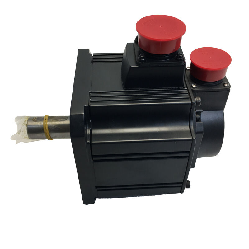
Mitsubishi HC-SFS352B (HCSFS352B) — 3.5kW AC Servo Motor with Electromagnetic Brake, Straight Shaft, 2000 rpm, MELSERVO J2-Super Series
Product Overview
Part Number: HC-SFS352B
Also Searched As: HCSFS352B, HC SFS 352B, HC-SFS-352B
Series: Mitsubishi MELSERVO HC-SFS (J2-Super Generation)
Classification: Medium-Inertia AC Brushless Servo Motor — 3.5 kW, 200V class, 2000 rpm, Straight Shaft, Spring-Applied Electromagnetic Brake
Two Features That Define This Motor
Every motor in the HC-SFS 2000 rpm family shares the same 17-bit absolute encoder, the same IP65 protection, the same medium-inertia design philosophy, and the same J2-Super amplifier platform. What separates one variant from another within any given capacity are the shaft configuration and the presence or absence of a brake. For the HC-SFS352B, both of those choices have been made in a specific direction, and understanding why they were made that way explains exactly which applications this motor belongs in.
Straight shaft. No keyway, no flat. The smooth cylindrical shaft OD accepts precision servo couplings, bellows couplings, disc couplings, and friction-clamp hubs of all standard types. For the majority of 3.5kW servo applications — ball-screw coupled feed axes, belt-driven gantry stages, direct-coupled winding drives — a straight shaft with a properly sized coupling is the cleaner and simpler interface.
Spring-applied electromagnetic brake. The coil must be continuously energised with 24V DC to keep the shaft free. Remove that voltage for any reason — E-stop, power loss, planned servo-off, panel fault — and the spring immediately pushes the brake disc against the friction surface. The axis stops mechanically and stays stopped, without depending on servo electronics, PLC logic, or any active system to hold it. At 3.5kW and 16.7 Nm continuous torque, the loads this motor typically drives are substantial enough that this fail-safe characteristic is not a convenience feature. It is a safety requirement.
Technical Specifications
| Parameter |
Value |
| Part Number |
HC-SFS352B |
| Rated Output |
3,500 W (3.5 kW) |
| Supply Voltage |
200V class (3-phase 200–230V AC) |
| Rated Speed |
2,000 rpm |
| Maximum Speed |
3,000 rpm |
| Rated Torque |
16.7 Nm |
| Peak Torque |
50.1 Nm |
| Encoder Type |
17-bit serial absolute |
| Encoder Resolution |
131,072 ppr |
| Shaft Type |
Straight (no keyway) |
| Electromagnetic Brake |
Spring-applied, electrically released (24V DC) |
| Flange Size |
176 × 176 mm |
| Protection Rating |
IP65 |
| Oil Seal |
Fitted |
| Inertia Class |
Medium inertia |
| Ambient Temperature (Operation) |
0°C to +40°C |
| Storage Temperature |
−15°C to +70°C |
| Vibration Resistance (X axis) |
24.5 m/s² |
| Vibration Resistance (Y axis) |
29.4 m/s² |
| Compatible Amplifiers |
MR-J2S-350A / MR-J2S-350B / MR-J2S-350CP |
| Series Generation |
MELSERVO J2-Super |
| Status |
Discontinued — available as stock |
Why Spring-Applied Brakes Belong on This Class of Motor
The physics of a 3.5kW vertical or inclined servo axis create a specific problem that servo lock alone cannot solve.
When the MR-J2S-350 amplifier is enabled and the servo is active, the position loop closes through the 17-bit encoder and the amplifier continuously supplies the current needed to hold commanded position. That works, reliably, under normal operating conditions. The problem is what happens when normal operating conditions end — not gradually, but instantly. An E-stop drops the servo enable signal. A mains interruption cuts amplifier power. A panel fault trips the main contactor. In any of these scenarios, servo lock ends immediately and the gravitational force acting on the axis load begins accelerating the mass downward.
At 3.5kW, the loads this motor typically drives — heavy Z-slides on machining centres, substantial gantry saddles, loaded pallet lift mechanisms, heavy rotary tables tilted off horizontal — have enough mass that unrestrained gravitational movement is not just a positioning error. It is a mechanical event that can damage tooling, fixtures, workpieces, and machine structure, and can injure personnel.
The spring-applied brake on the HC-SFS352B addresses this directly. The spring holds the brake disc against the friction surface by default. The coil must work continuously against the spring to keep the shaft free. The moment coil current stops — for any reason at all — the spring closes the brake. No software, no signal, no relay timing, no PLC sequence is required to make this happen. The brake applies passively and immediately, every time, regardless of what caused the power loss.
This is why the "-B" suffix on the part number is not merely an option. For vertical and gravity-loaded axes at this power level, it is the specification that makes the installation safe.
16.7 Nm Continuous, 50.1 Nm Peak: Working Through the Numbers
Sixteen point seven Newton-metres is a substantial sustained torque for a motor on a 130 × 130 mm... wait — the HC-SFS352B is on the 176 × 176 mm flange, the larger frame. At 3.5kW this is where the HC-SFS range moves to the medium-large frame, and the torque numbers reflect that.
To put 16.7 Nm in practical context: on a 10mm pitch ball screw with 90% efficiency, 16.7 Nm of continuous motor torque sustains approximately 9.4 kN of axial cutting or feed force. That covers medium-to-heavy machining centre table axes and large transfer machine feed mechanisms at continuous production feed rates without pushing the motor toward its thermal limit. For winding drives in tension control mode, 16.7 Nm maintained at 2,000 rpm provides a useful working range across roll diameter variation on medium-format winding stations.
The 50.1 Nm peak — exactly three times the continuous figure — handles the acceleration and deceleration transients. A 3.5kW axis making rapid positioning moves cycles through brief peak torque phases at the start and end of each traverse, spending the majority of the cycle at or below continuous torque during constant-velocity operation. The J2-Super amplifier's electronic thermal model tracks the cumulative heating effect of this duty cycle and alarms well before the winding temperature reaches a damaging point.
For vertical axis design, Mitsubishi's documentation carries a consistent recommendation: keep the sustained gravitational torque component — the torque the motor must supply continuously to support the load against gravity during motion — at 70% or below the rated continuous torque. At 16.7 Nm rated, that ceiling sits at approximately 11.7 Nm of sustained gravitational load. Axes approaching that figure should incorporate a mechanical counterbalance to reduce the continuous torque demand on the motor during motion. The spring-applied brake removes all torque demand entirely during standstill, but during the axis's moving phases, the gravitational load component is carried by the motor, and this 70% guideline governs the safe operating boundary.
Brake Installation: Sequencing and Wiring
The spring-applied brake on the HC-SFS352B requires a dedicated 24V DC circuit in the machine panel — it is not powered through the MR-J2S-350 amplifier's servo output. The panel design must include a suitably rated 24V DC supply for the brake coil, a brake relay with appropriately rated contacts, surge suppression across the coil terminals, and interlock logic that coordinates brake release and engagement with the amplifier's servo enable sequence.
Release sequence — brake opening: The servo must reach the enabled and servo-lock state before the brake coil is energised and the brake releases. Releasing the brake before servo lock is established allows the gravitational load to accelerate the axis before the amplifier can respond. On a 3.5kW vertical axis with a heavy load, this slip can be large enough to trigger a following error alarm, cause a mechanical collision, or produce a position error that disrupts the production cycle. The MR-J2S-350's MBR (Magnetic Brake Release) output signal provides an amplifier-managed contact specifically for sequencing the brake relay — the amplifier signals when servo lock is established and the brake can safely release.
Engagement sequence — brake closing: The correct procedure is to decelerate the axis to rest under servo control first, then engage the brake to hold the stopped position, then remove servo enable. Applying the brake to a moving axis — even at low speed — generates heat in the friction disc and produces wear. On axes with frequent servo-off cycles, following this three-step sequence rather than applying brake and removing servo simultaneously extends brake service life measurably.
Surge suppression: When the brake coil de-energises, the collapsing magnetic field produces an inductive voltage spike that can damage relay contacts and affect adjacent electronics. A flyback diode across a DC brake coil — or a varistor/RC network for AC — is mandatory. This is standard industrial panel practice for any inductive load; the brake coil is no exception. Size the suppressor to the coil's inductance and the relay contact rating; the Mitsubishi servo motor instruction manual and the relay manufacturer's application data provide the reference values.
Absolute Encoder on a Braked Vertical Axis
The 17-bit serial absolute encoder at 131,072 ppr on the HC-SFS352B is standard J2-Super equipment, but its value on a braked vertical axis goes beyond the resolution number.
The multi-turn absolute counter is maintained through power-off periods by the A6BAT battery in the MR-J2S-350 amplifier. Combined with the spring-applied brake, this creates a specific operational advantage: when the machine shuts down — whether at end of shift, on E-stop, or on unplanned power loss — the brake holds the axis mechanically at whatever position it stopped, and the encoder retains the exact shaft angle in memory throughout the outage. On restart, the controller reads the absolute position immediately without any shaft movement required.
For a heavy vertical axis on a production machine, this means: the axis parks safely, the brake holds it there, and when power returns, the machine knows exactly where the axis is and can resume production directly. No homing movement, no reference-finding sequence, no risk of inadvertent contact with a fixture or workpiece during the startup motion to find a reference marker. The combination of absolute encoder and fail-safe brake is what makes a large-capacity vertical servo axis both safe at rest and operationally efficient at restart.
Battery maintenance: Replace the A6BAT when the MR-J2S-350 displays a low-battery alarm. On a braked vertical axis specifically, a counter reset from battery depletion requires a reference-return cycle — which means moving the axis under defined conditions to find the home position before production can resume. On a machine where that movement carries risk or requires manual clearance of the work area, treating the low-battery alarm as an immediate maintenance item rather than a deferred one is straightforward risk management.
Compatible Amplifiers
The HC-SFS352B pairs with the MR-J2S-350 amplifier family — the 3.5kW capacity J2-Super platform. Three interface variants:
MR-J2S-350A accepts pulse-train position commands and analog speed or torque references from external CNC controllers and PLCs. All control modes — position, speed, torque, and switched combinations P/S, S/T, T/P — are available. RS-232C connects to MR Configurator for commissioning, parameter setting, and fault diagnosis. This is the standard choice for machine tool feed axes and general industrial positioning applications where the axis command source is an external controller.
MR-J2S-350B connects to Mitsubishi A-series and Q-series motion controllers via SSCNET fiber-optic serial bus. All axis commands, encoder feedback, alarm data, and monitoring signals travel over the fiber network. For coordinated multi-axis machines — vertical axes that must move in synchronised relationship with horizontal axes, portal systems with linked Z and X feeds, multi-axis transfer machines — the SSCNET bus provides the real-time axis coupling that pulse and analog interfaces cannot achieve.
MR-J2S-350CP incorporates built-in single-axis positioning with up to 31 stored point-table positions, activated by digital I/O or CC-Link network command. For standalone vertical lift, indexed press feed, or pallet elevator axes that do not require real-time coordination with other axes, the CP eliminates the cost and complexity of a dedicated motion controller.
All three amplifiers provide the MBR (Magnetic Brake Release) output for brake relay sequencing, support the full J2-Super protective function suite, and include real-time auto-tuning and adaptive vibration suppression.
Compatibility notes: The HC-SFS352B requires an MR-J2S-350 amplifier. It is not compatible with the first-generation MR-J2-350 amplifier, which cannot read the 17-bit J2-Super encoder. For machines running original MR-J2-350 hardware, the HC-SF352B (same mechanical specification, 14-bit encoder, spring-applied brake) is the correct motor. Not compatible with MR-J3 or MR-J4 amplifiers without a renewal adapter kit.
HC-SFS 2000 rpm Braked Family: Where the 352B Sits
| Model |
Output |
Rated Torque |
Peak Torque |
Flange |
| HC-SFS202B |
2,000 W |
9.55 Nm |
28.6 Nm |
176 × 176 mm |
| HC-SFS352B |
3,500 W |
16.7 Nm |
50.1 Nm |
176 × 176 mm |
| HC-SFS502B |
5,000 W |
23.9 Nm |
71.6 Nm |
176 × 176 mm |
| HC-SFS702B |
7,000 W |
33.4 Nm |
100 Nm |
176 × 176 mm |
The HC-SFS352B occupies the second position in the braked 176 × 176 mm range. All four models share the same mounting interface — a machine frame built for any one of them accommodates all without mechanical modification. The torque step from the HC-SFS202B (9.55 Nm) to the HC-SFS352B (16.7 Nm) is approximately 75%, which becomes the relevant comparison when a vertical axis running near the continuous torque ceiling of the 2kW unit needs more sustained torque capacity rather than simply more peak capacity.
Within the 3.5kW capacity at 2000 rpm, the full shaft-and-brake matrix runs: straight shaft no brake (HC-SFS352), straight shaft with brake (HC-SFS352B), keyed shaft no brake (HC-SFS352K), and keyed shaft with brake (HC-SFS352BK). All four use the MR-J2S-350 amplifier. The choice between straight and keyed shaft is made by the mechanical coupling interface; the choice between brake and no brake is made by whether the axis has a gravitational load component.
Typical Applications
Vertical Z-axis on large CNC machining centres. Heavy spindle heads and Z-slides on large-format vertical machining centres, gantry mills, and horizontal boring mills. The spring-applied brake holds the Z-axis mechanically at E-stop and power-off; the absolute encoder eliminates homing on restart; 16.7 Nm continuous provides the force budget for heavy spindle assembly weight plus cutting load reaction forces on the Z-feed during face milling and boring operations.
Servo-driven pallet and workpiece lift mechanisms. Pallet elevators, part lifts, and vertical transfer stations on machining cells and flexible manufacturing systems. These mechanisms carry defined payloads repeatedly through vertical travel ranges, must hold position under load at each station while operations complete, and must restart to exact known positions without homing. The HC-SFS352B's combination of fail-safe brake and absolute encoder serves this requirement directly.
Vertical press ram and die cushion drives. Servo-actuated press ram axes, die cushion servo drives, and servo-controlled straightener or leveller axes on press lines where the ram must hold position precisely at any point in the stroke, including during tooling changes, adjustment stops, and emergency stops.
Heavy inclined feed axes on machining and forming equipment. Inclined pallet changers, angular slide feeds, and tilted transfer mechanisms on machining centres and forming equipment where the axis weight component creates a sustained gravitational torque demand. The brake protects against runback when servo power is removed; the 70% torque guideline governs how much gravitational load the motor can handle during motion.
Industrial robot joint axes with gravity loading. Shoulder and elbow joint drives on heavy industrial robots and large servo-driven articulation axes on welding, handling, and assembly machines where joint rotation under gravity creates a sustained torque demand and fail-safe holding is a functional safety requirement.
Frequently Asked Questions
Q1: What is the difference between the HC-SFS352B and the HC-SFS352?
Both are 3.5kW, 2000 rpm, J2-Super motors with straight shafts, 17-bit encoders, and identical electrical specifications on a 176 × 176 mm flange. The only difference is the brake. The HC-SFS352 has no brake — position at rest is maintained by amplifier servo lock. The HC-SFS352B has a spring-applied electromagnetic brake that engages mechanically whenever 24V is removed from the brake coil. For confirmed horizontal axes with no gravitational load, the no-brake HC-SFS352 is simpler and lighter. For vertical axes, inclined feeds, and any gravity-loaded mechanism, the HC-SFS352B's fail-safe brake is the required specification.
Q2: Can the HC-SFS352B be installed as a direct replacement for an HC-SF352B on a machine running an MR-J2-350 amplifier?
Mechanically yes — both motors share the same 176 × 176 mm flange, shaft diameter, and brake connector arrangement. The amplifier compatibility, however, is the deciding factor. The HC-SF352B has a 14-bit encoder compatible with both MR-J2-350 and MR-J2S-350 amplifiers. The HC-SFS352B has a 17-bit encoder that requires an MR-J2S-350 amplifier only. Installing the HC-SFS352B on a machine running a first-generation MR-J2-350 amplifier will produce an encoder communication fault. Match the motor generation to the amplifier generation.
Q3: Does the brake engage when the servo is disabled at end of cycle, or only on power loss?
The brake engages whenever the 24V brake coil supply is removed, regardless of reason — planned servo-off at end of cycle, E-stop, power interruption, or relay de-energisation. For planned servo-off, the recommended sequence is: decelerate the axis to rest under servo control, energise the brake coil to hold the stopped position mechanically, then remove servo enable. This sequence prevents brake engagement on a moving axis, which generates heat and wear. Many machine designs use the MR-J2S-350's MBR output signal to manage this sequence automatically through the amplifier's internal timing.
Q4: Where is the absolute encoder battery, and what happens if it is not replaced promptly?
The Mitsubishi A6BAT lithium cell is housed in the MR-J2S-350 amplifier, not in the motor. It maintains the multi-turn absolute counter through all power-off periods. Replace it at the first low-battery alarm from the amplifier. A fully depleted battery resets the multi-turn counter — the absolute position data is lost. On the next startup, the controller will not know the axis position and a reference-return cycle is required before production can resume. On a braked vertical axis where homing movement requires careful axis clearance preparation, this is a meaningful production interruption that a timely battery replacement prevents entirely.
Q5: What surge suppression is required for the brake coil wiring, and why?
The brake coil is an inductive load. When the relay de-energises and cuts current to the coil, the collapsing magnetic field induces a voltage spike that can arc relay contacts and potentially couple noise into adjacent control electronics. A flyback diode across the coil terminals (for DC brake circuits) or a varistor or RC snubber (for AC circuits) absorbs this spike and protects the relay contacts. This is a standard requirement for any inductive coil in an industrial panel — not specific to Mitsubishi brakes. Omitting it shortens relay contact life and introduces an EMC risk. Size the suppressor to the coil's inductance and rated voltage; the motor instruction manual and relay manufacturer's data provide the reference parameters.

 Your message must be between 20-3,000 characters!