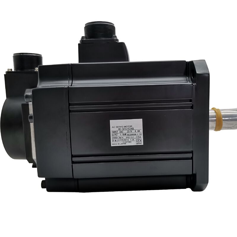
Mitsubishi HC-SFS1524B (HCSFS1524B) — 1.5kW, 400V Class AC Servo Motor with Electromagnetic Brake, 2000 rpm, Straight Shaft, MELSERVO J2-Super Series
Product Overview
Part Number: HC-SFS1524B
Also Searched As: HCSFS1524B, HC SFS 1524B, HC-SFS-1524B
Series: Mitsubishi MELSERVO HC-SFS (J2-Super Generation)
Classification: Medium-Inertia AC Brushless Servo Motor — 1.5 kW, 400V class, 2000 rpm, Straight Shaft, Spring-Applied Electromagnetic Brake
What This Motor Is
Two things define the HC-SFS1524B completely relative to the rest of the HC-SFS 1.5kW family.
The first is the 400V class supply voltage — the "24" in the part number. The HC-SFS152B is the mechanically identical 200V version of this same motor. The HC-SFS1524B winds those same stator poles for operation on 380–480V AC infrastructure, draws roughly half the line current at equivalent power, and pairs with the MR-J2S-200_4 amplifier rather than the MR-J2S-200. For factories and machine builders on European or international 400V supplies, this eliminates the transformer that would otherwise be needed to run 200V-class Mitsubishi servo drives. Same motor performance, directly connected to the local supply.
The second is the electromagnetic brake — the "B" suffix. This is a spring-applied, electrically released holding brake integrated into the rear of the motor. The spring applies the brake pads to the disc when the brake coil is de-energised; energising the coil with 24V DC lifts the pads and releases the shaft for motion. The practical consequence is critical: the brake is engaged by default and releases only when power is applied to the coil. A power loss — planned or unexpected — automatically applies the brake and holds the axis. For vertical axes and gravity-loaded mechanisms, this is exactly the behaviour needed.
Beyond those two characteristics, the HC-SFS1524B is the same 17-bit absolute encoder motor on a 130 × 130 mm flange at IP65 as every other motor in the HC-SFS 1.5kW 2000 rpm family.
Technical Specifications
| Parameter |
Value |
| Part Number |
HC-SFS1524B |
| Rated Output |
1,500 W (1.5 kW) |
| Supply Voltage |
400V class (3-phase 380–480V AC) |
| Rated Speed |
2,000 rpm |
| Maximum Speed |
3,000 rpm |
| Rated Torque |
7.16 Nm |
| Peak Torque |
21.6 Nm |
| Encoder Type |
17-bit serial absolute |
| Encoder Resolution |
131,072 ppr |
| Shaft Type |
Straight (no keyway) |
| Electromagnetic Brake |
Spring-applied, 24V DC release |
| Flange Size |
130 × 130 mm |
| Protection Rating |
IP65 |
| Oil Seal |
Fitted |
| Inertia Class |
Medium inertia |
| Ambient Temperature (Operation) |
0°C to +40°C |
| Compatible Amplifiers |
MR-J2S-200A4 / MR-J2S-200B4 / MR-J2S-200CP4 |
| Series Generation |
MELSERVO J2-Super |
| Status |
Discontinued — available as stock |
The Brake: Spring-Applied, Electrically Released
Among the various types of motor brakes used in industrial machinery, the spring-applied electromagnetically released design — sometimes called a fail-safe brake or a normally closed brake — has a specific and important characteristic that distinguishes it from alternatives: it fails safe.
The brake coil must be continuously energised with 24V DC to keep the shaft free to rotate. Remove power from the coil for any reason — an E-stop command, a panel fault, a power outage, a deliberate servo-off sequence — and the spring immediately pushes the brake disc against the friction surface. The axis stops and stays stopped, mechanically, regardless of whether the amplifier is active or whether servo lock is in effect.
This is the correct design for any axis that could cause injury or machine damage if it moved unexpectedly. A vertical spindle head. A vertically mounted rotary table. A servo-driven Z-axis on a machining centre or drill. A counterweighted gantry arm where the counterweight is imperfect and a net downward force acts on the servo axis. An inclined conveyor that would run back under gravity without resistance. In all of these applications, the spring-applied brake is not a convenience — it is a functional requirement.
For horizontal axes on symmetrically loaded mechanisms where no gravitational force acts in the direction of shaft rotation, servo lock alone holds the position adequately and a brake adds complexity without providing functional benefit. The HC-SFS1524B is specifically intended for the applications where that brake is genuinely required.
Brake Sequencing: What the Amplifier Needs to Know
The electromagnetic brake on the HC-SFS1524B requires a separate 24V DC power circuit for the brake coil — it is not powered through the servo amplifier's U/V/W output. The machine's panel design must include a 24V DC power supply rated for the brake coil current, a brake relay with appropriate surge suppression, and interlock logic that coordinates brake engagement and release with the servo enable sequence.
The sequence matters. The Mitsubishi servo motor instruction manual is explicit: when releasing the brake, always confirm the servo is ON before releasing. An axis that releases its brake before the amplifier has established servo lock will move under gravity or load until the amplifier catches up. On a vertical axis with significant load, this slip can be large enough to cause a collision or position error alarm. The interlock that prevents this is not optional.
The MBR (Magnetic Brake Release) signal available on the MR-J2S-200_4 amplifier provides a convenient output for this interlock — the amplifier can signal the brake relay as part of its enable sequence, ensuring the release occurs in the correct order relative to servo lock establishment. Consult the amplifier instruction manual for the recommended sequence timing, which varies depending on the axis dynamics.
On stop: engage the brake before removing servo enable. Leaving the axis to decelerate to zero on servo lock and then applying the brake — rather than applying the brake simultaneously with removing servo enable — ensures the axis is already at rest when the brake pads contact the disc. This extends brake disc life significantly on axes with frequent servo-off cycles.
400V in a 130 × 130 mm Frame
The 130 × 130 mm flange HC-SFS motors at 400V occupy a useful design niche: machines that need a compact motor footprint, operate on 400V infrastructure, and require a vertical or gravity-loaded axis that needs a holding brake at rest.
The capacity range available in this combination — 400V class, 130 × 130 mm, with brake — runs from the HC-SFS524B at 500W through the HC-SFS1024B at 1kW to the HC-SFS1524B at 1.5kW. The HC-SFS1524B is the ceiling of the compact 130 × 130 mm frame in this voltage class. The next step up in capacity — the HC-SFS2024B at 2kW — comes with the larger 176 × 176 mm flange, which means a new motor mounting interface. If the machine frame was designed for the 130 × 130 mm footprint and 1.5kW is adequate for the axis torque budget, the HC-SFS1524B is the correct and final answer.
At 7.16 Nm continuous and 21.6 Nm peak, the 1.5kW 2000 rpm operating point handles a wide range of real-world vertical axis requirements — ball-screw driven Z-axes with moderate table and tooling mass, servo-driven lift mechanisms, vertical transfer stations, and press-feed axes where position must be held at any point in the stroke without drift.
17-Bit Absolute Encoder and Vertical Axis Operation
On a braked vertical axis, the 17-bit serial absolute encoder earns its value in a specific way that is less obvious than it is on a horizontal positioning axis.
Consider what happens when a vertical servo axis is shut down at the end of a production shift — or more urgently, when it stops mid-stroke on an E-stop. The brake holds the position mechanically. The encoder retains the multi-turn absolute shaft angle in memory, backed by the A6BAT battery in the MR-J2S-200_4 amplifier. When the machine restarts, the controller reads the current absolute position from the encoder, establishes servo lock, then releases the brake in the correct sequence. The axis is immediately ready without any reference-return movement.
Contrast this with an incremental encoder: on restart, the axis position is unknown. A home-return cycle is required, which means moving the axis — potentially through the load's gravity range — to find the reference marker before production can begin. On a vertical Z-axis in a machining centre or a vertically travelling robot arm, this homing movement requires careful sequencing and is a non-trivial addition to the startup procedure. The absolute encoder eliminates it.
For machines that may experience unexpected stops — either by alarm, by E-stop, or by power loss — the combination of spring-applied brake and absolute encoder means the axis stops safely, stays where it stopped, and restarts from exact known position. That is the design the HC-SFS1524B provides.
Compatible Amplifiers
Three 400V class MR-J2S-200 amplifier variants support the HC-SFS1524B:
MR-J2S-200A4 is the general-purpose analog and pulse-train interface amplifier. It accepts position commands as pulse trains from external CNC controllers, PLCs, or indexers, and speed or torque commands as analog voltage inputs. Position, speed, and torque control modes are all available, as are the switched-mode combinations P/S, S/T, and T/P. RS-232C connects to MR Configurator setup software. This is the standard choice for most machine tool and industrial automation applications where the axis command comes from an external controller.
MR-J2S-200B4 connects to Mitsubishi A-series and Q-series motion controllers via SSCNET fiber-optic serial bus. All position data and monitoring information travel over the fiber link — there is no separate analog or pulse wiring to the axis. For coordinated multi-axis systems under a Mitsubishi motion controller, this is the correct amplifier. The real-time synchronisation that SSCNET provides is particularly valuable on multi-axis machines where vertical axes must move in coordination with horizontal ones.
MR-J2S-200CP4 incorporates built-in positioning functionality. Up to 31 target positions are stored as point table data inside the amplifier and activated by I/O signals or CC-Link network commands. For standalone vertical positioning axes — lift stations, servo-driven press feeders, Z-axis indexers on assembly equipment — where a full motion controller is not required, the CP4 provides the positioning intelligence locally.
All three amplifiers include the MBR (Magnetic Brake Release) output signal for coordinating the brake relay timing with the servo enable/disable sequence.
Voltage class note: The MR-J2S-200_4 amplifiers are 400V class only and must not be connected to a 200V supply. The "4" suffix on both motor and amplifier must match throughout the system.
HC-SFS 400V Braked Family: Where the 1524B Sits
| Model |
Output |
Rated Torque |
Peak Torque |
Flange |
Amplifier |
| HC-SFS524B |
500 W |
2.39 Nm |
7.16 Nm |
130 × 130 mm |
MR-J2S-60_4 |
| HC-SFS1024B |
1,000 W |
4.78 Nm |
14.4 Nm |
130 × 130 mm |
MR-J2S-100_4 |
| HC-SFS1524B |
1,500 W |
7.16 Nm |
21.6 Nm |
130 × 130 mm |
MR-J2S-200_4 |
| HC-SFS2024B |
2,000 W |
9.55 Nm |
28.6 Nm |
176 × 176 mm |
MR-J2S-200_4 |
| HC-SFS3524B |
3,500 W |
16.7 Nm |
50.1 Nm |
176 × 176 mm |
MR-J2S-350_4 |
| HC-SFS7024B |
7,000 W |
33.4 Nm |
100 Nm |
176 × 176 mm |
MR-J2S-700_4 |
The HC-SFS1524B is the highest-capacity motor in the 400V braked family that fits a 130 × 130 mm flange. Moving up to the HC-SFS2024B means accepting a larger frame and re-engineering the motor mounting interface. For machine designs that have committed to the 130 × 130 mm footprint, the 1524B is the highest-output, highest-torque option available before the frame size increases.
Typical Applications
Vertical Z-axis on machining centres and drilling machines. The archetypal braked servo application: a vertically travelling spindle head or Z-slide where the weight of the spindle, tool, and slide mechanism would drop under gravity if servo current were removed. The spring-applied brake holds the Z position mechanically at E-stop and power-off. The absolute encoder eliminates homing on restart. The 400V rating connects directly to the machine's main supply without a transformer.
Servo-driven press and stamping machine feeds. Vertical ram drives and servo-actuated die cushion axes on presses where position must be held precisely at any point in the stroke, including during mid-cycle stops. The combination of 7.16 Nm continuous torque, 21.6 Nm peak for acceleration, and a fail-safe brake suits these mechanisms on European-voltage machines.
Lift stations and transfer machine vertical axes. Part lift, pallet elevator, and vertical transfer shuttle axes on assembly and welding transfer machines. These mechanisms run at moderate speed, carry defined payloads, and must hold position at each station under load while the station operation completes. The absolute encoder means the lift position is known immediately on any restart.
Robot joint axes on 400V platforms. Secondary robot joint drives — shoulder, elbow — where European machine standards require a holding brake on any axis that would move under gravity when servo power is removed. The compact 130 × 130 mm frame suits robot arm geometries where motor packaging is constrained.
Vertical feed axes on CNC grinding and EDM machines. Grinding wheel head and electrode Z-feeds where the axis must park in a known position at machine-off and resume from that exact position without any homing movement that could contact the workpiece or damage the electrode. The brake holds; the absolute encoder reports; the axis restarts cleanly.
Frequently Asked Questions
Q1: What is the difference between the HC-SFS1524B and the HC-SFS152B?
They are the same motor at different supply voltages. The HC-SFS152B is a 200V class motor producing 7.16 Nm continuous torque and requiring an MR-J2S-200A/B/CP amplifier. The HC-SFS1524B is the 400V class equivalent — same frame, same torque, same brake, same 17-bit encoder — requiring an MR-J2S-200A4/B4/CP4 amplifier. For machines operating on 400V infrastructure, the 1524B is the direct choice; the motor and amplifier connect to the supply without a step-down transformer.
Q2: What voltage and current does the electromagnetic brake coil require?
The spring-applied brake on the HC-SFS1524B releases with 24V DC applied to the brake coil. This 24V supply must come from the machine's panel — it is separate from the motor power supply and the servo amplifier output. The brake relay and its 24V supply must be sized and sequenced appropriately. Surge suppression (diode or varistor) across the coil terminals is required to protect the relay contacts when the coil is de-energised.
Q3: Can the brake be used as a dynamic stopping brake during deceleration?
No. The electromagnetic brake on the HC-SFS1524B is a holding brake, not a service brake. It is designed to hold a stationary axis — not to decelerate a moving one. Applying the brake while the motor is running will wear the friction surfaces rapidly and may damage the brake mechanism. The correct sequence is: decelerate the axis to rest under servo control, then engage the brake to hold the stopped position.
Q4: Where is the absolute encoder battery, and how does it work with a braked vertical axis?
The backup battery — Mitsubishi A6BAT — is in the MR-J2S-200_4 amplifier, not in the motor. It maintains the multi-turn absolute counter through power-off events. On a braked vertical axis, this means the axis stops and holds its position mechanically when power is removed, and the encoder retains that exact position in memory. On restart, the controller reads the absolute position immediately — no homing movement required. Replace the A6BAT when the amplifier triggers a battery-low alarm; a depleted battery resets the absolute counter and requires a reference-return cycle.
Q5: Is the HC-SFS1524B compatible with MR-J3 or MR-J4 amplifiers?
No. The HC-SFS1524B requires a 400V class MR-J2S-200 amplifier (A4, B4, or CP4 variant). It is not directly compatible with MR-J3 or MR-J4 amplifiers. For new machine designs where J2-Super hardware is no longer available, the current-generation equivalent would be drawn from the HG-SR or HF-SP series with an MR-J4 400V amplifier — but that requires replacing both motor and amplifier together, along with verifying cable and connector compatibility.

 Your message must be between 20-3,000 characters!