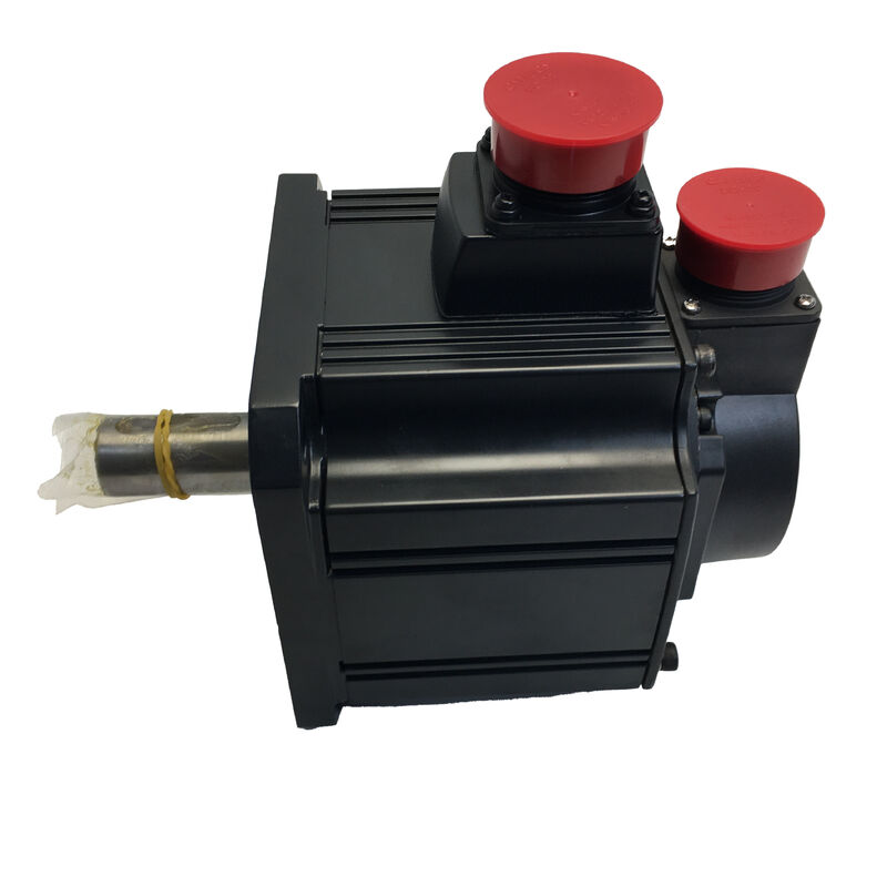
Mitsubishi HC-SFS102BG1 — 1kW AC Geared Servo Motor, Brake + G1 Reduction Gear, MELSERVO-J2S Series
Product Identification
Part Number: HC-SFS102BG1
Also Searched As: HCSFS102BG1, HC-SFS-102BG1
Series: Mitsubishi MELSERVO HC-SFS (J2-Super Generation)
Motor Type: AC Brushless Geared Servo Motor — Straight Shaft, Electromagnetic Brake, G1 Flange-Type Reduction Gear
What This Motor Delivers
Three engineering requirements drive the specification of the HC-SFS102BG1: a need for higher output torque than a 1kW motor can produce directly, a fail-safe mechanical hold when servo power is removed, and a compact, self-contained assembly that installs into the machine without a separately aligned external gearbox. This motor addresses all three at once.
The base HC-SFS102 produces 4.78 Nm continuously at 2,000 rpm. After the G1 general industrial flange-type reduction gear unit — available in ratios from 1/5 through 1/25 — that output torque multiplies proportionally while the shaft speed reduces accordingly. At a 1/20 ratio with typical gear efficiency, the output shaft delivers approximately 81–86 Nm continuously at 100 rpm. The spring-applied electromagnetic brake holds that output shaft position mechanically the moment 24V DC is removed, regardless of what the amplifier or control system is doing.
The 17-bit serial absolute encoder on the motor shaft — 131,072 positions per revolution — retains multi-turn absolute position through any power interruption via the A6BAT battery in the MR-J2S amplifier. The machine knows exactly where the axis is on every restart, without a homing cycle.
For a 1kW axis that must hold a gravity load, drive a slow mechanism at high torque, and restart precisely after any stop condition, the HC-SFS102BG1 covers the complete set of requirements in a single bolted-on assembly.
Technical Specifications
| Parameter |
Value |
| Part Number |
HC-SFS102BG1 |
| Base Motor Output |
1,000 W (1 kW) |
| Supply Voltage |
200V AC class (3-phase) |
| Rated Current |
5.3 A |
| Base Motor Rated Speed |
2,000 rpm |
| Base Motor Maximum Speed |
3,000 rpm |
| Base Motor Rated Torque |
4.78 Nm |
| Base Motor Maximum Torque |
14.4 Nm |
| Encoder |
17-bit serial absolute (131,072 ppr), motor shaft |
| Shaft Type |
Straight |
| Electromagnetic Brake |
Spring-applied, 24V DC release, fail-safe (motor shaft, before gear) |
| Reduction Gear Type |
G1 — General industrial, flange-type shaft output |
| Available Gear Ratios |
1/5, 1/9, 1/15, 1/20, 1/25 (stamped on gear housing) |
| Motor Flange Size |
130 × 130 mm |
| Motor Protection |
IP65 |
| Gear Section Protection |
IP44 |
| Oil Seal |
Fitted (motor shaft) |
| Ambient Temperature |
0°C to +40°C |
| Compatible Amplifiers |
MR-J2S-100A / MR-J2S-100B / MR-J2S-100CP |
| Series |
MELSERVO J2S (J2-Super) |
| Origin |
Made in Japan |
| Product Status |
Discontinued — available stock |
The Gear Unit: Output Torque That Changes the Application Profile
A bare 1kW servo motor at 2,000 rpm is a capable axis drive for a specific range of loads — moderate torque at mid-range speed. The G1 gear unit fundamentally changes the operating envelope. Instead of 4.78 Nm at up to 2,000 rpm, the system can deliver high torque at low shaft speeds, opening up applications that the motor alone simply cannot reach.
The relationship is straightforward: output shaft speed equals motor rated speed divided by the gear ratio; theoretical output torque equals motor rated torque multiplied by the gear ratio, minus gear losses. At a 1/20 ratio, the output shaft turns at 100 rpm and produces approximately 81–86 Nm of continuous torque (at 85–90% gear efficiency). At 1/9, the output runs at around 222 rpm with roughly 38–40 Nm continuous. At 1/5, you get approximately 400 rpm at 20–21 Nm.
The specific ratio installed in this unit is marked on the gear housing nameplate — always confirm that figure before setting the amplifier's electronic gear ratio parameters.
Motor-shaft encoding and its effect on output resolution is worth understanding for precision applications. The 17-bit encoder reads 131,072 positions per motor revolution. Because each output shaft revolution corresponds to multiple motor revolutions at the gear ratio, the effective encoder count per output revolution is the motor resolution multiplied by the ratio. At 1/20, that produces over 2.6 million effective counts per output shaft revolution — fine enough that the encoder is never the limiting factor in positioning accuracy on axes of this type.
The Electromagnetic Brake: Position Hold Through the Gear Ratio
The brake is located on the motor shaft, between the encoder assembly and the gear input stage. Spring pressure clamps the friction disc when 24V DC is absent; energising the coil holds it open. The fail-safe logic is inherent: power absent means shaft clamped — the safe state requires no active signal.
Because the load connects to the motor through the gear ratio, the effective holding force at the gear output shaft is the motor-shaft brake holding torque multiplied by the ratio. At 1/20, what would be a modest motor-shaft hold torque becomes a substantial output-shaft hold — more than adequate for the light vertical actuators, compact indexing mechanisms, and low-speed transfer drives that this motor typically serves.
Three wiring and sequencing points that apply at this capacity:
The MR-J2S amplifier's MBR (electromagnetic brake interlock) output must govern the brake relay. MBR delays brake engagement until the amplifier has confirmed the motor has decelerated to rest. Engaging the spring against a still-rotating motor shaft causes premature brake wear and can generate mechanical shock in the gear train. Even at 1kW, repeated brake engagement against motion compounds rapidly into shortened brake service life.
A surge absorber wired directly across the brake coil terminals is not optional. The coil's inductive transient at switch-off damages relay contacts and amplifier digital outputs without suppression. Place the absorber at the motor-end connector, not at the relay.
For vertical axes, Mitsubishi's guidance recommends keeping the static unbalanced torque at the motor shaft within 70% of the motor's rated torque — approximately 3.3 Nm at the motor for this motor. Through the gear ratio, that corresponds to a significantly larger allowable unbalanced load at the output shaft. Where the gravitational load exceeds this threshold, mechanical counterbalancing should supplement the servo and brake system.
Amplifier Compatibility and Commissioning
The HC-SFS102BG1 pairs with the MR-J2S-100 class amplifier. From the amplifier's perspective, the motor it is driving is the HC-SFS102 — the encoder protocol, motor recognition, and current control are unchanged by the gear unit. Three interface variants cover the main control architectures:
MR-J2S-100A — General-purpose analog/pulse command. Accepts step/direction or analog speed/torque from CNC and PLC systems. The standard choice for most machine tool and automation applications.
MR-J2S-100B — SSCNET fiber-optic bus under a Mitsubishi motion controller. Position commands arrive over the network from an A-series or Q-series controller; encoder feedback loops through the same fiber link.
MR-J2S-100CP — Built-in positioning with a stored point table, CC-Link or I/O commanded. For standalone applications not requiring a dedicated external motion controller.
At commissioning, one parameter adjustment is essential: the amplifier's electronic gear ratio (CMX/CDV in MR-J2S parameter terminology) must reflect the actual installed reduction gear ratio. This setting establishes the correct relationship between commanded position pulses and actual output shaft movement. Setting it incorrectly — or leaving it at the default for a direct-drive motor — will produce axis position errors, overshoot, or following error alarms on the first JOG test. Always read the ratio off the gear housing nameplate and verify the parameter before the first powered move.
HC-SFS 2000 rpm Range — 1kW in Context
| Model |
Output |
Rated Torque |
Peak Torque |
Flange |
| HC-SFS52 series |
500 W |
2.39 Nm |
7.16 Nm |
130 × 130 mm |
| HC-SFS102 series |
1,000 W |
4.78 Nm |
14.4 Nm |
130 × 130 mm |
| HC-SFS152 series |
1,500 W |
7.16 Nm |
21.5 Nm |
130 × 130 mm |
| HC-SFS202 series |
2,000 W |
9.55 Nm |
28.6 Nm |
176 × 176 mm |
The HC-SFS102BG1 shares the 130 × 130 mm flange with the 500W and 1.5kW models in the HC-SFS 2000 rpm family. All carry the 17-bit absolute encoder and MR-J2S amplifier requirement as standard.
G1 vs G1H: Mounting Geometry Choice
The HC-SFS102 range is available with two general industrial gear configurations. The G1 (flange type) used in this motor mounts the gear housing face against the machine structure, with the output shaft projecting forward in-line with the motor axis. It is the correct choice for machine designs where the motor-gearbox assembly drops into a bore or mounts against a flat face plate.
The G1H (leg type) uses foot-mounting pads on the gear housing base and suits layouts where the motor must sit alongside rather than behind the gear housing — conveyor drive rails, base-mounted chain drive stations, and similar base-supported installations.
Both use the same motor body, encoder, and brake. The choice between them is purely mechanical — driven by the machine's mounting geometry and available installation envelope.
Typical Applications
Small CNC auxiliary and indexing drives. Chip conveyor drives, tool magazine indexing mechanisms, and pallet carousel drives on compact machining centres use 1kW geared servo motors where the low output shaft speed and multiplied torque suit the conveyor or carousel load, the absolute encoder confirms index position precisely on every cycle, and the brake holds each index station during machining operations.
Vertical actuators on light handling systems. Small vertical lift axes — component lifts, workpiece presenters, lightweight transfer mechanisms with a gravity load component — combine the 1kW output with the brake's fail-safe hold and the gear ratio's multiplied holding force. The axis holds position through every power-off event without relying on servo current.
Compact rotary indexing tables. Small-format rotary index tables for assembly, inspection, and test fixtures use geared servo motors on the table drive input. The gear unit reduces the output shaft to the speed range that suits the table mechanism; the brake holds angular position during the work dwell; the 17-bit encoder provides the angular resolution needed for repeatable multi-station indexing.
Winding and tension axes on compact converting equipment. Small roll-to-roll systems — label converters, narrow web printers, small laminating lines — use 1kW geared servo drives on the winding and braking axes. The motor runs in torque control mode across a wide speed range; the gear ratio keeps the motor in an efficient operating window regardless of roll diameter.
Conveyor station servo drives. Individually servo-controlled conveyor stations on assembly and test lines use geared servo drives for precise speed control and accurate position hold at each station. The G1 flange mounting integrates cleanly into standard conveyor framing, and the absolute encoder ensures accurate station position on every shift start without a homing sequence.
Frequently Asked Questions
Q1: Which amplifiers are compatible with the HC-SFS102BG1?
The HC-SFS102BG1 requires a MR-J2S-100 class amplifier from the MELSERVO-J2S platform. The three main variants are the MR-J2S-100A (general-purpose analog/pulse command), MR-J2S-100B (SSCNET fiber-optic bus for Mitsubishi motion controllers), and MR-J2S-100CP (built-in positioning with CC-Link). All support the 17-bit serial encoder. This motor is not compatible with original MR-J2-100 amplifiers or with MR-J3 / MR-J4 amplifiers. Always set the amplifier's electronic gear ratio parameters to match the installed reduction gear ratio before commissioning.
Q2: How does the G1 reduction gear affect the output torque and speed of the motor?
The gear reduces output shaft speed and proportionally multiplies torque. At the motor's 2,000 rpm rated speed and 4.78 Nm, a 1/20 gear ratio produces approximately 100 rpm at the output shaft with roughly 81–86 Nm of continuous torque (accounting for 85–90% gear efficiency). A 1/9 ratio gives approximately 222 rpm at around 38–40 Nm. The specific ratio installed is stamped on the gear housing nameplate — confirm this value before setting amplifier parameters.
Q3: The brake is on the motor shaft, not the output shaft. How does this affect the holding force at the load?
Because the load connects through the gear unit, the effective holding force at the output shaft equals the brake's motor-shaft holding torque multiplied by the gear ratio. A higher ratio provides proportionally greater output-side hold from the same brake. The brake is a holding device only — it must engage only after the motor has stopped, sequenced through the MR-J2S amplifier's MBR (brake interlock) output. Always fit a surge absorber directly across the brake coil terminals to protect relay and amplifier circuits at switch-off.
Q4: Does the 17-bit encoder battery sit inside the motor or in the amplifier?
The Mitsubishi A6BAT lithium battery that maintains the absolute encoder's multi-turn position counter is inside the MR-J2S servo amplifier — not in the motor or gear assembly. Replace it when the amplifier displays a low-battery alarm, before full depletion. A depleted A6BAT resets the absolute position counter, requiring a reference return cycle before production can resume. The motor itself requires no battery maintenance.
Q5: What is the protection rating of this motor, and does it cover the gear section?
The motor body carries IP65 — fully sealed against dust ingress and protected against water jets from any direction. The reduction gear housing section is rated IP44, which covers splash water but not sustained directed water jets or wash-down. If the installation involves heavy coolant exposure or regular wash-down cleaning, verify that IP44 is adequate for the gear housing location, and consider supplemental sealing or splash guards where necessary.

 Your message must be between 20-3,000 characters!