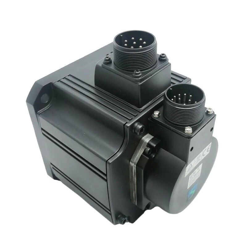
logo
Guangzhou Sande Electric Co.,Ltd.
Email Sales01@sande-elec.com TEL: 86--18620505228
Home > Products > Industrial Servo Motor >
One New Mitsubishi Servo Motor HC-SFS81K HCSFS81K
  • One New Mitsubishi Servo Motor HC-SFS81K  HCSFS81K

One New Mitsubishi Servo Motor HC-SFS81K HCSFS81K

Place of Origin JAPAN
Brand Name MITSUBISHI
Certification CE ROHS
Model Number HC-SFS81K
Product Details
Condition:
New Factory Seal(NFS)
Item No.:
HC-SFS81K
Origin:
JAPAN
Highlight: 

mitsubishi industrial servo motor

,

mitsubishi yaskawa ac servo motor

Payment & Shipping Terms
Minimum Order Quantity
1 pcs
Packaging Details
original packing
Delivery Time
0-3 days
Payment Terms
T/T, PayPal, Western Union
Supply Ability
100 pcs/day
Product Description

Mitsubishi HC-SFS81K (HCSFS81K) — 850W AC Servo Motor, Keyed Shaft, No Brake, 1000 rpm, MELSERVO-J2S Series

Product Identification

Part Number: HC-SFS81K

Also Searched As: HCSFS81K, HC-SFS-81K Series: Mitsubishi MELSERVO HC-SFS (J2-Super Generation)

Motor Type: AC Brushless Servo Motor — Keyed Shaft, No Brake, 1000 rpm, 200V AC


Overview

The Mitsubishi HC-SFS81K is an 850W medium-inertia AC brushless servo motor from the MELSERVO-J2S platform, rated at 1,000 rpm and fitted with a machined keyway on the drive shaft. No electromagnetic brake is included. It is the correct specification for applications that need the substantial continuous torque that a 1,000 rpm motor generates from its rated output — combined with a positive, key-and-hub shaft coupling interface — on horizontal axes and drives where servo lock provides adequate position hold at rest.

At 1,000 rpm, 850 watts of output means roughly 8.12 Nm of continuous rated torque. That figure is nearly double what a comparable 850W motor would produce at 2,000 rpm. This is the core reason the 1,000 rpm family gets specified for certain applications: not for speed, but for sustained torque at moderate shaft velocities. Rotary table inputs, winding stations, slow conveyor drives, and low-speed direct-drive mechanisms that need genuine torque authority without gearing — these are the natural home of this motor.

The keyed shaft ensures the torque path through the coupling is mechanically positive, independent of friction. The 17-bit serial absolute encoder provides 131,072 positions per revolution of feedback to the MR-J2S amplifier, retaining multi-turn absolute position through power interruptions via the A6BAT battery in the amplifier.


Technical Specifications

Parameter Value
Part Number HC-SFS81K
Rated Output 850 W (0.85 kW)
Supply Voltage 200V AC class (3-phase)
Rated Current Approx. 5 A
Rated Speed 1,000 rpm
Maximum Speed 1,500 rpm
Rated Torque 8.12 Nm
Maximum Torque 24.4 Nm
Encoder 17-bit serial absolute (131,072 ppr)
Shaft Type Keyed (with keyway)
Electromagnetic Brake None
Inertia Class Medium inertia
Flange Size 130 × 130 mm
Protection Rating IP65
Oil Seal Fitted
Ambient Temperature 0°C to +40°C
Compatible Amplifiers MR-J2S-100A / MR-J2S-100B / MR-J2S-100CP
Series MELSERVO J2S (J2-Super)
Origin Made in Japan
Product Status Discontinued — available stock

The 1000 rpm Operating Point: Torque Where It Counts

Power equals torque multiplied by angular velocity. Fix the power at 850W and lower the rated speed, and the rated torque rises proportionally. The HC-SFS81K at 1,000 rpm produces 8.12 Nm continuously — the same wattage at 2,000 rpm would yield approximately half that, around 4 Nm. This is not a subtle difference. It determines whether a given axis can handle sustained load torque without the motor running near its thermal ceiling, and it determines whether gearing is needed between the motor and the driven mechanism.

For machine designers working with slow-speed loads, the 1,000 rpm family often simplifies the drive train. A conveyor shaft that needs to run at 150 rpm under moderate torque load, for example, might be driven from a 3,000 rpm motor through a 1/20 gearbox — or from a 1,000 rpm motor through a 1/6 or 1/7 stage. The 1,000 rpm motor reduces the gear ratio required, which generally means lower backlash, better energy efficiency through the gear stage, and simpler mechanical design. In some cases, direct coupling becomes viable.

The 24.4 Nm peak — three times the continuous figure — covers the transient demand. Getting a loaded mechanism from rest to operating speed, reversing direction at high cycle rates, or absorbing shock loads from the driven process all draw on the peak. The three-to-one ratio gives the amplifier enough headroom to command aggressive acceleration without the motor exceeding its continuous rating during the motion phase.


Keyed Shaft: Positive Torque Connection at This Capacity

At 8.12 Nm continuous and 24.4 Nm peak, the shaft coupling interface on the HC-SFS81K carries real mechanical load. A friction-clamp hub on a plain straight shaft relies on the clamping force remaining sufficient under all operating conditions — which includes cyclic loading, directional reversals, and the progressive effects of fretting between hub bore and shaft OD over years of production service.

The keyway changes the fundamental mechanism. Torque flows through the key in shear, not through surface friction. Under the reversing and cyclic loads that production machinery delivers, a correctly fitted keyed connection degrades far more slowly than a marginal friction interface — and its failure mode, when it eventually does occur, is usually visible (visible key or keyway wear) rather than the insidious micro-slip that friction interfaces can develop without obvious external signs.

Applications that naturally specify keyed shafts at this capacity:

Timing belt drives where the belt tension and cyclic tooth engagement loads create alternating torque inputs at the motor shaft. These are precisely the conditions that gradually induce micro-slip in friction-only interfaces. Gear hub connections where angular registration between shaft and gear matters for correct tooth mesh. Chain sprocket drives in transfer and material handling systems where chain engagement impulses arrive repeatedly. Worm gear inputs on small rotary tables where the gear is keyed to the motor shaft.

From Mitsubishi's servo motor instruction manual: When fitting a hub onto a keyed motor shaft, use the shaft-end threaded hole and a drawbolt to pull the hub axially into position rather than hammering or pressing it on. At this frame size, axial impact during hub installation carries through the shaft to the encoder disc at the motor's rear. The damage may not cause an immediate fault — it tends to manifest as intermittent position errors and encoder alarms under vibration, difficult to trace back to the installation event. The drawbolt method eliminates this failure mode.


No Brake: The Application Logic

Position hold at rest on the HC-SFS81K comes from the amplifier's servo lock — the position loop stays active, the encoder monitors shaft position continuously, and corrective current maintains zero following error. For horizontal axes and mechanisms where no net force acts in the direction of shaft rotation during a hold, this is both adequate and the simplest architecture.

Adding a brake to these axes requires relay wiring, surge absorbers, 24V DC current, MBR interlock logic in the safety circuit, and periodic brake disc inspection. None of that overhead translates into any functional benefit when the load naturally stays put on servo lock alone.

The calculation changes for vertical axes, inclined slides, gravity-loaded arms, and any mechanism where the load applies a continuous torque in one direction when the servo is not actively commanding motion. Those axes belong to the HC-SFS81BK (keyed shaft with spring-applied brake). The HC-SFS81K is correct specifically for the horizontal and symmetrically loaded application category where servo lock handles everything.


17-Bit Encoder and Absolute Position

The J2-Super encoder at 131,072 ppr is the same device carried by every motor in the HC-SFS family, from the 500W HC-SFS52 through the 7kW HC-SFS702. At 1,000 rpm, the high resolution provides a cleaner velocity signal to the speed loop — each inter-sample increment is a finer angular step, so the velocity estimate the amplifier computes from successive encoder readings contains less granularity noise. At this moderate operating speed, that translates to smooth, stable velocity regulation even under variable load conditions.

The absolute function requires the A6BAT lithium cell in the MR-J2S amplifier. It maintains the multi-turn position counter through any power interruption, however brief or extended. Every restart — routine shutdown, alarm trip, emergency stop recovery — brings the axis up in its exact last known absolute position. No reference return, no homing cycle, no production time consumed in repositioning.

Replace the A6BAT when the amplifier's low-battery alarm triggers. Allowing the battery to deplete fully resets the multi-turn counter, and the machine cannot resume production until a reference return is completed.


Compatible Amplifiers

The HC-SFS81K pairs with the MR-J2S-100 class amplifier — the 1kW J2-Super platform. All three interface variants support the 17-bit encoder and the motor's approximately 5A rated current:

MR-J2S-100A — General-purpose analog/pulse interface. Accepts step/direction pulse trains and ±10V analog commands. Position, speed, and torque control modes. Setup via MR Configurator through RS-232C. The standard choice for CNC and PLC-driven systems.

MR-J2S-100B — SSCNET fiber-optic bus. Connects to Mitsubishi A-series or Q-series motion controllers for coordinated multi-axis systems. Position commands travel over the fiber network; encoder data returns through the same link.

MR-J2S-100CP — Built-in positioning with stored point table. Up to 31 positions stored in the amplifier, triggered by I/O or CC-Link. Suitable for standalone indexed positioning without a dedicated motion controller.

The HC-SFS81K is not compatible with original MR-J2-100 amplifiers — the 17-bit J2S encoder protocol is unreadable by first-generation MR-J2 hardware. For machines running MR-J2-100 amplifiers, source the HC-SF81K (J2 generation, 14-bit encoder, same mechanical specification).


HC-SFS 1000 rpm Family — Where 850W Sits

Model Output Rated Torque Peak Torque Flange
HC-SFS81 series 850 W 8.12 Nm 24.4 Nm 130 × 130 mm
HC-SFS121 series 1,200 W 11.5 Nm 34.4 Nm 130 × 130 mm
HC-SFS201 series 2,000 W 19.1 Nm 57.3 Nm 176 × 176 mm
HC-SFS301 series 3,000 W 28.6 Nm 85.9 Nm 176 × 176 mm

All motors in this family use the 17-bit serial absolute encoder, 200V AC class supply, IP65 protection, and oil-sealed shaft as standard. The HC-SFS81K is at the smaller end of the 1000 rpm range with a 130 × 130 mm flange, sharing its mounting footprint with the HC-SFS121 series directly above it.

Each capacity point is available in all shaft-and-brake combinations: straight shaft no brake, straight shaft with brake (B), keyed shaft no brake (K), and keyed shaft with brake (BK). The shaft type and brake presence do not affect amplifier selection — all variants at a given capacity use the same amplifier class.


Typical Applications

Winding and material feed drives. Roll-to-roll material handling systems — coil straighteners, web accumulators, tape winding, wire spooling — use 1000 rpm servo drives in torque control mode to regulate web tension or winding torque continuously. The 800W capacity handles medium-weight roll systems, the 7.64 Nm continuous manages sustained tension load across the winding profile, and the keyed shaft suits the drive hub interface at the roll arbour or dancer coupling.

Rotary table and indexing station drives. Compact rotary index tables for assembly and inspection fixtures running at low output speeds use 1000 rpm servo motors where the high continuous torque allows direct drive to the table or through a single reduction stage without a multi-stage gearbox. The absolute encoder confirms angular position on every index cycle without a homing sequence.

Slow-speed conveyor and transfer axes. Servo-driven conveyor sections, cross-transfer drives, and part accumulation systems running at low surface speeds need continuous torque rather than high rpm. The HC-SFS81K delivers the torque at the speed range these mechanisms actually use, with the keyed shaft matching the sprocket or gear-coupled drive interfaces typical in conveyor design.

CNC lathe auxiliary and turret drives. Compact CNC lathe auxiliary axes — servo-driven tool turret indexing and sub-spindle feed drives on small-format turning centres — use 1000 rpm medium-inertia motors where the index cycle requires sustained torque at moderate speed. The 130 × 130 mm flange fits the constrained installation spaces in lathe headstock and turret drive compartments.

Tension-regulated unwind drives. Unwind stands on printing, laminating, and slitting lines run in torque control mode with the motor speed varying as roll diameter changes. The 1000 rpm motor stays within a sensible operating speed range across the full unwind profile without demanding unusual electronic gear ratio settings, and the keyed shaft handles the reversal torques common in braking-mode unwind drives.


Frequently Asked Questions

Q1: Which amplifiers are compatible with the HC-SFS81K?

The HC-SFS81K requires a MR-J2S-100 class amplifier. The three standard variants are the MR-J2S-100A (analog/pulse command), MR-J2S-100B (SSCNET fiber-optic bus for Mitsubishi motion controllers), and MR-J2S-100CP (built-in positioning). All support the 17-bit serial encoder. This motor is not compatible with original MR-J2-100 amplifiers, or with MR-J3 / MR-J4 amplifiers. For machines running first-generation MR-J2 hardware, source the HC-SF81K (J2 generation, 14-bit encoder) instead.

Q2: What is the difference between the HC-SFS81K and the HC-SFS102K at 1kW?

Both are keyed shaft, no-brake motors on a 130 × 130 mm flange with 17-bit encoders and MR-J2S-100 amplifier compatibility. The difference is the rated speed. The HC-SFS81K runs at 1,000 rpm with 7.64 Nm continuous torque. The HC-SFS102K runs at 2,000 rpm with 4.78 Nm continuous torque. Same power class, different torque-speed operating points. Choose the 81K where sustained torque at low shaft speed is the design requirement; choose the 102K where higher axis speed at moderate torque better suits the application.

Q3: Why does an 800W motor use the same MR-J2S-100 amplifier as the 1kW HC-SFS102?

The MR-J2S-100 is rated at 1kW, which covers both the 800W HC-SFS81 and the 1kW HC-SFS102 within its capacity envelope. Mitsubishi's amplifier pairing convention allows an amplifier to drive motors up to its rated capacity. The HC-SFS81K runs within the MR-J2S-100's current and power ratings comfortably, and this pairing is confirmed in the MR-J2S-100 series compatibility documentation.

Q4: Does the 17-bit encoder retain position through power loss, and where is the battery?

Yes. The 17-bit serial absolute encoder retains multi-turn position data through power-off using a Mitsubishi A6BAT lithium battery inside the MR-J2S servo amplifier — not in the motor. Replace the battery when the amplifier displays a low-battery alarm, before full depletion causes the absolute counter to reset. A depleted A6BAT requires a reference return cycle before production can resume.

Q5: Is a key supplied with the HC-SFS81K?

Mitsubishi's standard practice for keyed-shaft HC-SFS motors is to supply the keyway machined into the shaft without including a key in the motor packaging. Verify the keyway dimensions against the HC-SFS81 series servo motor instruction manual before ordering a key, and select one with correct width, height, and tolerance for the hub bore and the application's torque and duty cycle requirements.


Contact Us at Any Time

+86 18620505228
10/F,Jia Yue Building, Chebei Road,Tianhe district,Guangzhou,China
Send your inquiry directly to us