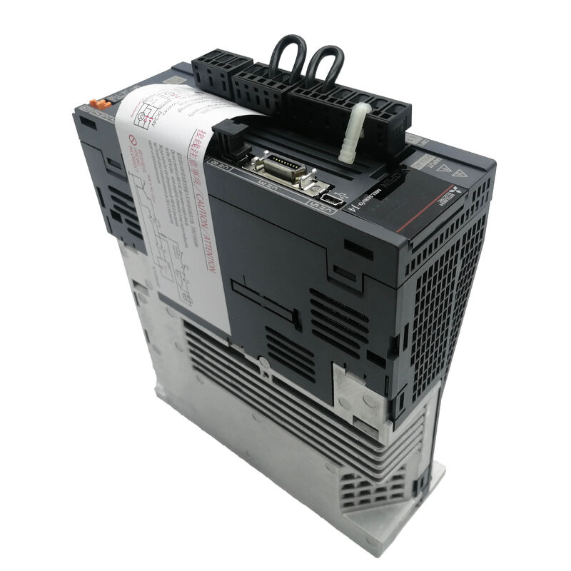
MR-J4-70B | MELSERVO-J4 Servo Amplifier — 0.75kW / SSCNET III/H / 5.8A / AC200V / STO SIL3 PL e / 8ms / IP20
SSCNET III/H — Optical Motion Network at 0.222ms Cycle
The MR-J4-70B uses SSCNET III/H (Servo System Controller NETwork III/High-speed) as its command interface. SSCNET III/H transmits servo commands over optical fibre — no electrical noise coupling between the motion controller and the drive, and no signal degradation across long cable runs.
The communication cycle is selectable: 0.222ms, 0.444ms, or 0.888ms. At 0.222ms, position, speed, and torque command updates from the motion controller reach the amplifier every 222 microseconds — fast enough for tight multi-axis synchronisation and contour following applications where axes must coordinate with microsecond-level consistency.
Position feedback travels back the same way. The 22-bit encoder feedback resolution means every degree of rotation is divided into over 1,400 steps for high-precision positioning.
Key Specifications
| Parameter |
Value |
| Output |
0.75 kW / 5.8A / 3-phase AC170V |
| Main Circuit Input |
AC200–240V 3-ph or 1-ph / 3.8A |
| Control Input |
AC200–240V 1-ph / 30W |
| SSCNET Cycle |
0.222 / 0.444 / 0.888ms |
| Encoder Resolution |
22-bit |
| Built-in Regen |
20W |
| Interface Power |
DC24V ±10% / 0.3A |
| Safety |
STO SIL3 / PL e / ≤8ms response |
| IP Rating |
IP20 |
| Temperature |
0–55°C operating |
| Altitude |
Up to 2000m |
STO — Safety Torque Off to SIL 3 / PL e
The MR-J4-70B integrates STO (Safe Torque Off) as a hardware safety function. STO cuts off the energy supply to the servo motor without requiring the drive to be powered down. The motor coasts to a stop with no torque applied. No relay or contactor in the motor cable path is needed to achieve this functional level of safety.
The certification covers EN ISO 13849-1:2015 Category 3 PL e, IEC 61508 SIL 3, and EN 62061 SIL CL 3 — the highest level for machine safety functions. Response time from STO input activation to energy cutoff is 8ms or less.
For machine builders who need to demonstrate functional safety compliance for emergency stop, guard door monitoring, or enabling device functions, the integrated STO removes the need for an external safety relay module in the drive output circuit.
Application Scenarios
Machine tool feed axis replacement: A CNC machining centre running a MELSERVO-J4 SSCNET III/H motion network develops a drive fault on the Y-axis. MR-J4-70B replacement restores the 0.75kW axis without network reconfiguration — the amplifier auto-detects its position on the optical network.
Pick-and-place machine servo axis: A packaging machine with synchronised X/Y motion uses J4 amplifiers networked via SSCNET III/H. The 0.222ms communication cycle provides tight axis coordination across all channels.
Safety-certified machine guard: A grinding machine with a guard door interlock wires the door contact to the MR-J4-70B's STO input. Opening the door immediately cuts motor torque to SIL 3 / PL e standard without a separate safety relay.
FAQ
Q1: Can the MR-J4-70B accept single-phase AC input?
Yes. The main circuit accepts either 3-phase or single-phase AC200–240V at 50/60Hz. Single-phase input is fully supported without derating for the 0.75kW capacity. The control circuit always uses single-phase AC200–240V separately from the main circuit.
Q2: Is the MR-J4-70B compatible with J3-series servo motors?
The MR-J4-70B provides a J3 compatibility mode. In this mode, the amplifier can operate with servo motors from the MELSERVO-J3 generation using J3-compatible encoder communication. Verify the specific motor model's compatibility with J3 mode in the MR-J4 series documentation before mixing J3 motors with a J4 amplifier.
Q3: What does the 2-channel analogue monitor output provide?
The two analogue monitor outputs provide real-time continuous voltage signals proportional to internal servo parameters — motor speed, torque output, position error, current, or other selectable quantities. An oscilloscope or a data logger connected to these outputs captures the servo's dynamic behaviour without interrupting operation. The monitor signals are independent of the SSCNET III/H communication path.
Q4: What are the requirements for the DC24V interface power supply?
The DC24V interface supply must be within ±10% of 24V and deliver at least 0.3A continuously. This supply powers the control circuit logic, input/output interfaces, and CN8 connector signals. A separate 24V supply from the main circuit power is required — the amplifier does not internally generate 24V from the AC mains input.
Q5: What are the full-closed loop capabilities of the MR-J4-70B?
Full-closed loop uses a second encoder — mounted at the machine's load side (linear scale, external rotary encoder) — as the primary position feedback rather than the motor's internal encoder. The machine-end encoder interface on the MR-J4-70B uses Mitsubishi high-speed serial communication. The 2-wire communication method supports full-closed loop without the cabling complexity of earlier encoder interfaces.


 Your message must be between 20-3,000 characters!