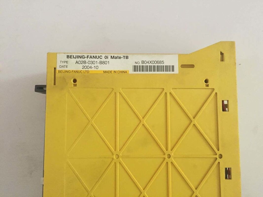
FANUC A02B-0301-B801 | Series 0i Mate-TB CNC Control System Unit — FSSB Servo Interface, A16B-3200-0495 CPU Card, PMC, Optional Graphics/RAM/ROM Cards, Lathe Platform
Part Number: A02B-0301-B801 Manufacturer: FANUC Corporation (Japan) Product Line: FANUC Series 0i — 0i-B Generation Variant: 0i Mate-TB (lathe/turning platform) Function: Complete CNC system control unit — the central hardware assembly containing the main CPU board, FSSB servo interface, PMC (Programmable Machine Controller), and provision for optional plug-in cards (graphics, RAM, ROM) as specified by the machine tool builder Main CPU Card: A16B-3200-0495 — the processor board carrying axis control, spindle control, PMC ladder execution, programme storage, and system memory Servo Interface: FSSB (FANUC Serial Servo Bus) — fibre-optic high-speed serial link to FANUC αi/βi series servo amplifiers Machine Configuration (0i Mate-TB): Turning machines — up to 4 controlled axes total, 2-axis simultaneous contouring (as standard Mate-TB configuration) Status: Legacy — 0i-B series (discontinued from new manufacture; available as repaired/refurbished/surplus units) Origin: Japan Applications: Spare part replacement and maintenance for lathes, turning centres, and turning machines originally equipped with FANUC Series 0i Mate-TB controls — common in machine tool brands including Mazak, Doosan, Takisawa, Leadwell, and various Asian and European lathe manufacturers of the 2000s era
Overview
The FANUC A02B-0301-B801 is the system unit for the FANUC Series 0i Mate-TB — the turning (lathe) variant of FANUC's compact high-performance CNC family from the early-to-mid 2000s. In the 0i control architecture, the system unit is the controller's core: the physical assembly that integrates the main CPU board, the FSSB servo interface circuitry, the PMC (FANUC's integrated PLC for machine signal management), and the connection infrastructure for optional function cards. Everything else in the control cabinet — the operator panel, the servo amplifiers, the spindle amplifier, the I/O units — connects to and from this central unit.
The "0i Mate" designation indicates a streamlined version of the full 0i series, optimised for cost-effective integration into smaller machines while maintaining compatibility with the full 0i software environment. The "-TB" further identifies this as the turning machine variant, pre-configured with the axis and spindle control software appropriate for lathe applications. In a typical 0i Mate-TB lathe installation, the system unit controls 2 servo axes (X and Z) plus the spindle, with the optional C-axis (spindle indexing) and Y-axis available as configuration upgrades through parameter and software options.
The A02B-0301-B801 is now encountered almost exclusively as a maintenance component — the control system for a lathe that was manufactured in the 2000s and is still in production service. When a system unit fails, or when an upgrade from an older 0i-B unit to a later revision is needed, the A02B-0301-B801 is the appropriate replacement hardware for machines that were originally fitted with this exact control generation.
Key Specifications
| Parameter |
Value |
| Series |
FANUC 0i Mate-TB (0i-B generation) |
| Main CPU |
A16B-3200-0495 |
| Servo Bus |
FSSB (FANUC Serial Servo Bus) |
| Machine Platform |
Turning (lathe) |
| Controlled Axes |
Up to 4 (2-axis standard) |
| PMC |
Integrated |
| Optional Cards |
Graphics, RAM, ROM (builder-specified) |
| Status |
Legacy spare / surplus |
| Origin |
Japan |
FSSB — FANUC Serial Servo Bus
The FSSB (FANUC Serial Servo Bus) is the high-speed digital communication link that connects the CNC system unit to the FANUC servo amplifiers (αi series SVM, βi series SVU) and spindle amplifier. Rather than the traditional analogue ±10V speed reference signal and separate encoder feedback cable, FSSB replaces all of these with a single fibre-optic cable loop running at 4Mbps. Over this single loop, the CNC sends position commands and receives position feedback for all connected axes — in the 0i Mate-TB installation, typically X-axis, Z-axis, and spindle — in a single synchronised communication cycle.
FSSB significantly reduces the wiring complexity in the machine's electrical cabinet. A three-axis lathe that previously required 9 signal cables between the CNC and the servo amplifiers (±10V speed reference and enable/alarm signals per axis) requires only 2 fibre-optic cables with FSSB — one from the system unit to the first amplifier, and a daisy-chain link between subsequent amplifiers. The fibre-optic medium is also inherently immune to the electromagnetic interference generated by the servo amplifiers' PWM switching — a practical benefit in the crowded electrical cabinets of CNC lathes.
The A16B-3200-0495 CPU Card
The main CPU card A16B-3200-0495 is the processing heart of the A02B-0301-B801 system unit. This card carries the CNC's main processor, the system DRAM for programme and data storage, the SRAM battery-backed storage for parameter and programme retention through power loss, the PMC processor and its ladder programme storage, the servo axis control DSP, and the FSSB communication interface. In other words, the vast majority of the control system's intelligence — axis interpolation, spindle control, programme execution, machine ladder scanning — executes on this single board.
The modular card architecture allows targeted board-level replacement when specific subsystems fail: if the SRAM data is corrupted, the battery can be replaced without disturbing the main processor; if the axis control DSP fails while other functions remain intact, board-level repair or replacement addresses the fault without replacing the complete system unit.
PMC — The Machine's Integrated PLC
FANUC's PMC (Programmable Machine Controller) is functionally a PLC embedded within the CNC system, running its ladder programme in parallel with the CNC's motion control functions. The PMC handles all of the machine's non-motion logic: door interlock signals, chip conveyor control, coolant pump management, chuck/tailstock hydraulic logic, tool turret positioning commands, safety relay monitoring, operator panel lamp control, and mode switching between manual, MDI, and automatic operation.
In the 0i Mate-TB, the PMC ladder is stored on the main CPU card and is specific to the machine tool builder's design. When an A02B-0301-B801 system unit is obtained as a spare, it may contain the original machine's PMC ladder and CNC parameters — or it may have been cleared. Before installing a replacement system unit, the machine tool builder's parameter backup and PMC ladder backup must be loaded. Without these, the machine cannot execute its proper machine-specific logic, regardless of the CNC hardware being functional.
Legacy Support — Maintaining 0i-B Machines
The FANUC 0i-B series was produced through approximately the mid-2000s, when 0i-C and subsequently 0i-D replaced it as the current generation. Machines built with 0i-B controls are now typically 15–25 years old, which means maintenance organisations must navigate a hardware generation that FANUC no longer manufactures new. Spare boards and system units for the 0i-B are available through three channels: FANUC's own spare parts inventory (diminishing), specialist CNC component dealers and refurbishers who maintain tested surplus stock, and repair services that restore failed boards to working condition.
The A02B-0301-B801 system unit is among the more widely available 0i-B components because of its broad deployment across many lathe makers in the 2000s. However, availability tightens yearly, and maintenance engineers responsible for fleets of 0i-Mate-TB machines are advised to hold at least one tested spare system unit per machine type to avoid extended production downtime during a control failure.
FAQ
Q1: The system unit was obtained as a spare. What parameters and data need to be loaded before the machine can run?
A replacement system unit needs three sets of data before the machine can operate: CNC system parameters (parameter backup from the original machine or machine tool builder documentation, typically loaded via memory card or RS-232); PMC ladder programme (the machine-specific PLC logic, backed up from the original control or obtained from the machine builder); and workpiece programme offsets and tool geometry data (from the machine operator's records). Without the correct PMC ladder, the machine's safety and interlock logic will not function. FANUC's 0i Mate-TB commissioning manual (B-63835EN) describes the parameter restoration procedure.
Q2: What servo amplifiers are compatible with the FSSB interface on the A02B-0301-B801?
The 0i Mate-TB system unit connects via FSSB to FANUC αi-series (SVM2, SVM3) and βi-series (SVU) servo amplifier modules.
The amplifier type must match the servo motor specifications (motor series, current rating, encoder type). Mixing αi amplifiers with βi motors or vice versa is not generally supported.
The machine tool builder's electrical drawing specifies the exact amplifier type and axis assignment.
When replacing a servo amplifier in an existing 0i Mate-TB machine, matching the original amplifier model and ensuring the FSSB node address is correctly set is essential.
Q3: Can the 0i Mate-TB A02B-0301-B801 be upgraded to 0i-C or 0i-D functionality?
Not directly — the A02B-0301-B801 hardware is generation-specific to the 0i-B software. Upgrading from 0i-B to 0i-C or 0i-D requires replacing the system unit and potentially the servo amplifiers, operator panel, and display with current-generation hardware.
FANUC's migration path for 0i-B machines involves complete control system replacement. While the PMC ladder may be adapted from 0i-B to 0i-D format with engineering effort, the motion parameters require re-tuning on the new hardware.
This type of control upgrade is typically a significant capital project, not a drop-in component swap.
Q4: What is the typical cause of A02B-0301-B801 system unit failure, and is board-level repair possible?
Common failure modes include SRAM battery failure (causing parameter and programme loss at power cycle), failed electrolytic capacitors on the power supply section (causing unstable voltages and erratic axis behaviour), failed FSSB interface ICs (causing servo communication faults), and corrupted boot firmware on the CPU card's Flash memory. Board-level repair by specialist FANUC repair centres addresses all of these except physical PCB damage.
The A16B-3200-0495 CPU card is the most commonly repaired sub-assembly.
FANUC authorised service centres and independent specialist repairers (DNC Electronics, MRO Electric, and equivalent companies in various regions) offer tested refurbished system units and board repair services.
Q5: What backup procedure should be performed before the system unit is removed from a running machine?
Before removing the system unit, create backups of: all CNC parameters (backup to memory card via the SYSTEM → PARAM → OPRT → (PUNCH) menu, or via RS-232 from the PCMCIA card slot); the PMC ladder programme (backed up via the PMC screen, LADDER → OPRT → SAVE); all workpiece offsets, tool geometry data, and macro variables (via the OFFSET → OPRT → PUNCH sequence).
Additionally, record the FSSB amplifier assignment table. Store these backups in two separate locations (memory card and PC). Without this data, restoring the machine to its operating condition after a hardware change requires the machine builder's support and can take days rather than hours.


 Your message must be between 20-3,000 characters!