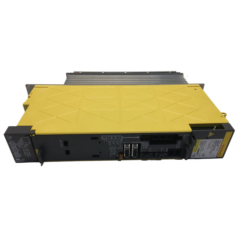
Fanuc A06B-6130-H002 | Beta i Servo Amplifier Unit BSVM1-20i — 6.8A, 200–240VAC, FSSB Fiber Optic, Built-In Power Supply, CNC 0i-MC / 0i-MD
Overview
The Fanuc A06B-6130-H002 occupies a distinct position in the Fanuc servo drive lineup because of something that makes it categorically different from the SVM-series amplifier modules used for main machine axes: it contains its own built-in power supply.
An SVM module — the kind that drives the X, Y, and Z axes on a typical Fanuc-controlled machining centre — sits on a shared DC bus and draws its power from a separate PSM (Power Supply Module). The A06B-6130-H002 does not work that way.
It takes AC power directly from the facility supply, rectifies it internally, and produces everything the servo loop needs from that single input connection.
The result is an amplifier unit that can be mounted anywhere on the machine — anywhere within cable reach of the AC supply and the FSSB fiber loop — without needing a DC bus connection to the main drive rack.
That self-contained power architecture is the reason this unit appears so frequently as a fourth-axis or auxiliary-axis amplifier on 0i-MC and 0i-MD controlled machines.
Machine builders who need to add a rotary table, a tool changer axis, or a pallet indexer to a machine that already has the main three-axis drive system configured can place the A06B-6130-H002 near the added axis, bring it AC power from the machine's main distribution, and run the FSSB fiber link from the CNC's servo card through the existing axis chain and on to this unit.
The machine's fourth axis appears in the CNC's servo configuration like any other FSSB axis — the fact that its amplifier has a different power architecture is transparent to the CNC's servo loop operation.
The FSSB fiber optic interface is the communication link that makes this possible.
Fanuc's serial servo bus transmits all position commands, speed references, and feedback data on a single optical fiber daisy-chain — no separate position command lines, no analog velocity references, no separate signal wiring.
The fiber optical link also provides complete galvanic isolation between the CNC's control electronics and the amplifier's power section, which eliminates ground loop interference paths that were common in earlier-generation servo systems with analog signal wiring.
At 6.8A maximum output current and a 50A internal transistor module, the A06B-6130-H002 is sized for the small-frame beta i series motors — the βiS4/4000 and βiS8/3000 are the most commonly paired motors.
These are compact, economical servo motors that Fanuc designed for exactly the kind of auxiliary axis application this amplifier serves: limited-space fourth-axis installations on small-to-mid-size machining centres, where a full-size alpha i motor and SVM module would be over-specified and over-sized.
Key Specifications
| Parameter |
Value |
| Unit Designation |
BSVM1-20i |
| Output Current |
6.8A |
| Input Voltage |
200–240V AC |
| Input Frequency |
50Hz / 60Hz |
| Interface |
FSSB (fiber optic) |
| Axis Count |
1 |
| Internal PSU |
Yes (self-contained) |
| Transistor Module |
50A (1 unit) |
| Wiring Board |
A20B-2101-0091 |
| Control Card |
A20B-2101-005x |
| Compatible Motors |
βiS4/4000, βiS8/3000 |
| CNC |
0i-MC, 0i-MD (typical) |
Self-Contained Architecture — Where It Matters
The significance of the built-in power supply is clearest when a machine builder faces the practical problem of where to put an additional servo axis on a machine that was not originally designed for it.
On a machine with an alpha i drive rack in the main electrical cabinet, the DC bus is sized for the axes originally specified.
Adding a fourth axis by inserting another SVM module means adding a module to the bus, which increases the DC bus load — the PSM's capacity must accommodate it.
The A06B-6130-H002 sidesteps this entirely. It does not load the existing DC bus.
The only additions to the existing electrical system are a circuit breaker and AC supply tap (for the unit's own input power) and an extension of the FSSB fiber chain.
The main drive system is architecturally untouched.
This is why machine builders, system integrators, and retrofit engineers reach for the beta i servo unit so consistently when adding axes to existing machines: it is the lowest-impact way to add an FSSB-interfaced servo axis to any 0i or compatible control system.
FSSB Communication and Axis Assignment
The FSSB fiber link passes through the A06B-6130-H002 via two fiber connectors — one in (from the CNC's servo card or the previous axis in the chain) and one out (to the next axis in the chain, if any).
This daisy-chain topology allows the CNC to address each axis in sequence.
The servo setup screen on the 0i CNC shows the FSSB axis map after system startup, and the A06B-6130-H002 appears in the chain at the position corresponding to its physical location in the fiber loop.
The axis number assigned to this unit in the CNC's parameter configuration must match the FSSB position to avoid axis assignment mismatches.
The FSSB operates at high speed and is the communication path for position commands, velocity references, and encoder feedback data — all carried on one optical fiber in each direction of the chain.
The fiber used is standard plastic optical fiber (POF) suitable for the distances involved within and between machine electrical cabinets.
Alarm and Protection Features
The A06B-6130-H002 monitors its own operating condition continuously. The 7-segment LED display on the front panel shows the drive state and alarm code. Key alarm conditions include:
Alarm 8 / Alarm OVC — Over-current in the output stage. Check the motor, motor power cable, and connector for winding faults or phase-to-phase shorts before assuming the amplifier's transistor module has failed.
Alarm 5 / Alarm LVDC — Low DC bus voltage inside the unit's built-in supply. On this self-contained unit, this points to the unit's internal rectifier or pre-charge circuit rather than a separate PSM, unlike the SVM series.
Alarm 2 — Cooling fan stopped. The fan is separately available and replaceable without exchanging the complete unit — a valuable serviceability feature on a drive that may be mounted in a location with limited airflow.
Leakage detection circuitry is also built in, monitoring for ground fault conditions in the motor output wiring. This provides an early warning mechanism for deteriorating motor winding insulation before a complete winding fault occurs.
FAQ
Q1: Can the A06B-6130-H002 drive alpha i series motors as well as beta i motors?
The A06B-6130-H002's 6.8A output current limits it to small-frame motors.
The beta iS4/4000 and βiS8/3000 are well within this rating. Small alpha i motors — αiS2/5000, αiS4/5000 — fall within the rated current at light to moderate loading, but this combination should be verified against Fanuc's motor-amplifier selection table before committing to a design.
Alpha i motors require the amplifier parameters to recognise the alpha i encoder protocol correctly. Any motor/amplifier pairing outside the published selection table should be validated with Fanuc or a qualified drive system engineer.
Q2: The unit has a built-in power supply — does this mean it needs no connection to the main drive rack's DC bus?
Correct. The A06B-6130-H002 takes AC input power from its own supply terminals and does not require any connection to the DC bus of the main alpha i drive rack.
Its only connections to the rest of the control system are the FSSB fiber optic link (daisy-chained through the servo axis map) and the emergency stop / MCC signal wiring as specified in the machine's electrical design.
This electrical independence is precisely what makes it suitable for remote axis placement.
Q3: What CNC series are compatible with the A06B-6130-H002?
The A06B-6130-H002 uses the FSSB fiber optic interface and is primarily designed for the Fanuc 0i-MC and 0i-MD control series.
It is also compatible with other Fanuc i-series controls that use FSSB servo communication — including the 16i/18i/21i-B platforms in FSSB configurations.
Compatibility requires the CNC's FSSB implementation to support the beta i amplifier unit's axis type; verify the CNC's servo selection guide for the specific control version being used.
Q4: If the transistor module inside the A06B-6130-H002 fails, can the unit be repaired, or must it be exchanged?
The 50A transistor module inside the unit is a separately available spare part and can be replaced by a qualified service engineer during a module-level repair.
This is an advantage over drives where the transistor module is integrated into the power board — the A06B-6130-H002's serviceable transistor module means a costly IPM fault does not necessarily require a full unit exchange.
The control card and wiring board are not sold separately; if either of these boards fails, a full unit exchange or board-level repair through a specialist is the resolution path.
Q5: After fitting a replacement A06B-6130-H002, what parameters must be set on the 0i CNC?
The primary parameter checks after a beta i servo unit replacement are: confirm the FSSB axis assignment on the servo setup screen matches the expected axis number for the fourth axis; verify the servo motor parameter (No. 2020 motor type) is set correctly for the beta i motor connected; and confirm the amplifier communication is established without FSSB alarm.
If the replacement unit has a different hardware revision than the original, any revision-specific parameter notes in the Fanuc beta i servo startup documentation should be reviewed. Reference return must be performed on the axis after confirming the servo loop is operating correctly.

 Your message must be between 20-3,000 characters!