Fanuc A06B-6087-H115 | Alpha Power Supply Module PSM-15 — 17.5kW, 200–230V AC 3-Phase, 63A Input, 283–325V DC Bus, Active Regeneration, CNC 16i / 18i / 21i
Overview
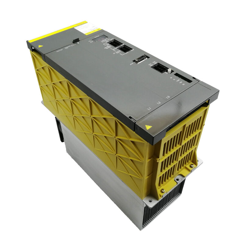
The Fanuc A06B-6087-H115 is the PSM-15 — Fanuc's 17.5kW continuous-rated power supply module for the alpha series drive system.
Its job is both simple and indispensable: take three-phase 200–230V AC from the facility electrical system, convert it to a regulated 283–325V DC bus, and distribute that bus to all the SVM servo and SPM spindle amplifier modules that share the drive rack.
Every watt of mechanical output from every motor the system drives passes through this module first.
That single-point role means the PSM-15's health is the health of the entire drive system — when it fails, nothing moves.
At 17.5kW continuous output and a 63A rated AC input at 200V, the PSM-15 is sized for mid-range machine configurations: a spindle amplifier module plus one or two servo axis combinations draws within this envelope under typical production cutting conditions.
The 63A input figure drives the electrical design of the machine's supply panel — the breaker, cable cross-section, and line filter ahead of the PSM must all accommodate this rated current plus the transient inrush at startup, which the recommended AC reactor (A81L-0001-0123) helps limit.
What makes the PSM-15 specifically the PSM and not the simpler PSMR (the regenerative resistor variant) is the active power regeneration front end. When servo or spindle motors decelerate, the kinetic energy stored in rotating masses flows back through the amplifiers toward the DC bus.
In a PSMR system, resistors burn this energy as heat.
In the PSM-15, an active switching circuit reverses the power flow direction and returns this energy to the three-phase AC supply.
For machines with high spindle inertia or frequent heavy deceleration events — tool changes on machining centres, repeated rapid positioning cycles — the thermal benefit inside the electrical cabinet is substantial.
Cabinet temperatures run lower, component life extends, and in some installations the regeneration contribution reduces measurable electricity consumption.
The PSM-15 is a 150mm wide module — noticeably wider than the 60–90mm SVM modules it powers — because of its thermal requirements.
Three 200A transistor modules generate heat that must be extracted continuously to keep junction temperatures within rated limits.
The external heatsink finned block, external fan (A90L-0001-0335/B), and internal fan (A90L-0001-0422) are the three paths through which this heat is managed.
All three must be operational for the PSM-15 to sustain rated output; a failed fan is not just a maintenance note — it is a developing thermal overload situation with a predictable outcome.
Key Specifications
| Parameter |
Value |
| Module Designation |
PSM-15 |
| Rated Input Voltage |
200–230V AC, 3-phase |
| Rated Input Current |
63A at 200V |
| Input Frequency |
50/60Hz |
| Rated DC Bus Output |
283–325V DC |
| Rated Output Power |
17.5kW |
| Module Width |
150mm |
| Transistor Modules |
Three × 200A |
| Wiring Board |
A20B-1006-0470 |
| Control Card |
A16B-2202-042x |
| External Fan |
A90L-0001-0335/B |
| Internal Fan |
A90L-0001-0422 |
| Regeneration |
Active (returns energy to AC supply) |
| Recommended Reactor |
A81L-0001-0123 |
| CNC |
Series 0-D, 15, 16i, 18i, 21i |
The DC Bus — Power Reservoir for All Axes
The 283–325V DC bus that the PSM-15 maintains is more than a power rail — it is an energy reservoir that all connected amplifier modules draw from simultaneously. When multiple servo axes accelerate at the same time, all of them pull current from the bus concurrently.
The PSM-15's front-end rectifier and filter capacitor bank must supply these simultaneous transient demands while holding the bus voltage within the regulated range.
If the combined peak current demand exceeds the capacitor bank's transient capability, the bus voltage sags and downstream modules detect the condition as a drive alarm.
PSM selection for a given machine should account not just for total continuous power but for the peak simultaneous demand profile.
A machine with a large spindle motor and three feed axes that all accelerate at the same time — during an aggressive rapid traverse following a tool change — presents a peak load substantially above the continuous figure.
The PSM's selection guidelines apply a simultaneous demand factor (typically 0.7–0.8) to the sum of all module rated powers to identify the continuous-equivalent demand.
Regeneration: Active Front End vs Resistor Discharge
The distinction between the PSM (active) and PSMR (resistor) designs is energy management. Every time a servo axis decelerates — and on a production machining centre this happens dozens of times per minute — the motor acts as a generator, pushing current back toward the DC bus.
The bus voltage rises as this energy accumulates. Something must handle that energy: in the PSMR, a braking resistor dissipates it as heat; in the PSM-15, the active front end switches to invert mode and feeds the energy back to the three-phase AC supply.
The difference in cabinet heat output is tangible on high-cycle machines.
Fewer joules of heat per hour inside the cabinet means the cabinet runs cooler, the thermal margin on all components is wider, and the electrical cabinet's cooling equipment — if any — runs less intensively.
The operating cost difference from recovering regenerated energy to the grid is secondary on a per-machine basis, but measurable over a fleet of machines across shifts.
Fan Maintenance and AL02/AL03 Alarm Response
The two fans in the PSM-15 serve different thermal zones.
The external fan (mounted outside the module) drives air through the external heatsink fins where the transistor modules' heat is conducted. The internal fan circulates air within the module housing to prevent hot spots on the control electronics.
Both fans are available as individual spare parts — a significant advantage over drive designs where fan failure requires complete module exchange.
AL02 (control circuit fan stopped) is the alarm that appears when the internal fan halts.
It is an early warning: the control electronics are not yet at risk immediately, but thermal margin is depleting.
Treatment as an urgent maintenance event is appropriate. AL03 (heatsink over-temperature) follows a failed external fan: the heatsink temperature climbs until protection triggers a shutdown to prevent transistor module damage.
The time between external fan failure and AL03 shutdown depends on ambient temperature, DC bus load, and the rate of heat generation in the transistors.
Scheduled preventive fan replacement — regardless of apparent fan condition — is sound practice on PSM-15 units operating in heavy production environments beyond five years of service.
Fan bearing wear is age-dependent and does not always present audible warning before failure.
Serviceable Components and Repair Approach
The PSM-15 is designed around the principle that a power module can be repaired rather than simply replaced.
The three 200A transistor modules are available as spare parts and can be replaced during an overhaul. Both fans are separately available.
The DC bus fuses and the battery (for the 24V control power section) are standard consumables.
The two main boards — wiring board A20B-1006-0470 and control card A16B-2202-042x — are the non-separable elements and are not sold as standalone spares; if either board has failed beyond component-level repair, the module as a whole requires exchange or specialist board-level repair.
FAQ
Q1: Can the A06B-6087-H115 PSM-15 power both alpha and alpha i series SVM amplifier modules on the same DC bus?
No. The A06B-6087 PSM family aligns with the original alpha amplifier generation (A06B-6079, A06B-6096 SVM families).
The alpha i generation uses the A06B-6110 series aiPS power supplies with a different DC bus hardware interface and control power distribution.
The two power supply generations are not cross-compatible within the same drive bus.
Any machine upgrading from alpha to alpha i amplifiers must also change the power supply module from the PSM to the aiPS architecture.
Q2: What determines whether a machine needs a PSM (active regeneration) or PSMR (resistor discharge)?
The choice depends on the regenerated power level during the machine's production cycle. If decelerations are infrequent or involve low-inertia loads, a PSMR suffices.
If the machine has a large spindle motor, frequent tool changes, or high-cycle aggressive positioning, the regenerated energy during deceleration may exceed the PSMR's resistor thermal rating — the resistor overheats and the machine cannot sustain production cycle rates.
Fanuc's PSM/PSMR selection procedure calculates the average regenerated power from the machine's motion profile; if the calculated figure exceeds the PSMR's capacity, the PSM is required.
Q3: AL01 appears on the PSM-15's display immediately at power-on — what does this indicate for this module class?
On the PSM-15 through PSM-30 class, AL01 indicates overcurrent in the main circuit AC input — the three-phase current drawn by the rectifier section has exceeded the protection threshold. This differs from the PSM-5.5 and PSM-11 where AL01 indicates an IPM fault.
For the PSM-15, check: the three-phase supply voltage balance at the PSM input terminals (voltage imbalance can cause apparent overcurrent), the incoming line fuses, and whether the AC reactor (A81L-0001-0123) is correctly installed and undamaged.
If AL01 persists with all downstream SVM modules disconnected from the bus, the fault is internal to the PSM.
Q4: How should the 63A rated input current be used to design the supply circuit ahead of the PSM-15?
The 63A is the continuous rated input at full 17.5kW output from 200V AC. The actual circuit protection must also account for startup inrush during DC bus pre-charge, which the AC reactor limits but does not eliminate.
Standard practice is to use a 80–100A rated circuit breaker ahead of the PSM-15 with an appropriate time-current trip characteristic that allows the inrush transient without nuisance tripping.
Cable cross-section should be sized for 63A continuous with appropriate derating for ambient temperature and conduit fill.
The AC reactor's impedance serves the dual purpose of inrush limiting and harmonic attenuation.
Q5: After fitting a replacement A06B-6087-H115, are there any parameter settings or startup procedures required on the CNC?
The PSM-15 does not carry CNC parameters — it operates autonomously within the alpha drive system.
After fitting a replacement, power up the CNC and confirm the PSM's front panel display shows the normal "0" or "running" state rather than an alarm code within the first few seconds of power application (the DC bus pre-charge sequence takes several seconds).
Verify the DC bus voltage at the SVM module connection points is within the 283–325V range using a voltmeter if available.
If the previous machine configuration was operating correctly with the failed PSM and no other changes have been made to the drive system, no parameter changes are required.

 Your message must be between 20-3,000 characters!