Fanuc A06B-6087-H126 | Alpha Power Supply Module PSM-26 — 29.8kW, 200–230V AC 3-Phase, 106A Input, 283–325V DC Bus, Active Regeneration, CNC 16i / 18i / 21i
Overview
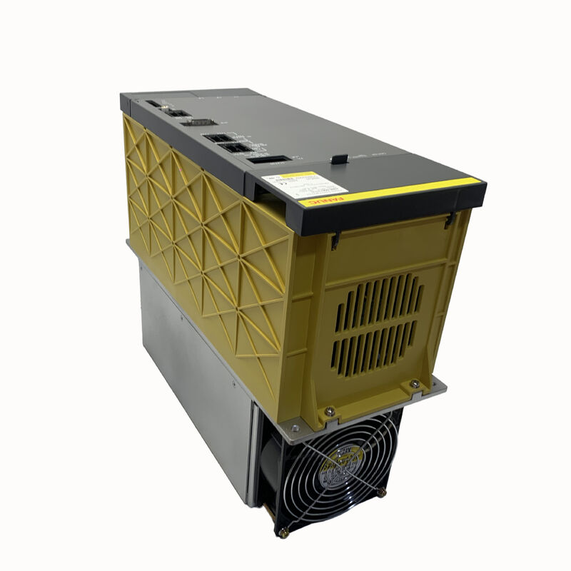
The Fanuc A06B-6087-H126 is the PSM-26 — one of the most widely deployed alpha power supply modules across the installed base of Fanuc-controlled CNC machine tools.
The 29.8kW continuous output rating and 106A input at 200V place it in the power class that covers a large share of medium-to-large machining centres and turning centres built around 16i/18i/21i controls: machines with a 7.5kW to 15kW spindle and two to four servo axes running simultaneously.
For this configuration profile, the PSM-26 provides the right power margin — enough headroom above typical simultaneous demand to avoid sustained operation at the module's thermal limit, without the cost and cabinet space of the larger PSM-37.
The PSM-26's reputation as one of the most reliable and commonly encountered modules in the A06B-6087 family is a product of both its design and its application fit.
Three 300A transistor modules — a higher current rating per transistor than many smaller PSM models — give the module capacity well above its 106A rated input, providing the transient peak margin needed during simultaneous multi-axis acceleration events without stressing the transistor junctions.
The active power regeneration front end returns deceleration energy from spindle and servo motors to the three-phase AC supply, reducing cabinet heat output and power consumption across repeated tool change and positioning cycles.
This module operates at the intersection of the alpha drive system's most common spindle amplifiers (A06B-6088 and A06B-6102 SPM series, typically for 5.5kW to 15kW spindle motors) and the standard alpha SVM servo amplifier families.
A machine with a single SPM spindle module and a three-axis SVM configuration is exactly the load profile the PSM-26 was sized for — common enough that the PSM-26 became effectively a standard fitting on a large number of CNC lathes and mid-range machining centres built throughout the 1990s and 2000s.
The A06B-6087-H126 has two documented hardware revisions (rev.A and rev.B) that differ in their wiring board specification (A20B-1006-0161 for rev.A, A20B-1006-0471 for rev.B) and in whether the product carries CE marking.
Functionally, both revisions are identical and interchangeable in the drive rack. The control card A16B-2202-0421 is common to both revisions; the #BM suffix variant uses A16B-2202-0424 as the control board.
Key Specifications
| Parameter |
Value |
| Module Designation |
PSM-26 |
| Rated Input Voltage |
200–230V AC, 3-phase |
| Rated Input Current |
106A at 200V |
| Input Frequency |
50/60Hz |
| Rated DC Bus Output |
283–325V DC |
| Rated Output Power |
29.8kW |
| Module Width |
150mm |
| Transistor Modules |
Three × 300A |
| Wiring Board |
A20B-1006-0161 (rev.A) / A20B-1006-0471 (rev.B) |
| Control Card |
A16B-2202-0421 |
| External Fan |
A90L-0001-0335/B |
| Internal Fan |
A90L-0001-0422 |
| Regeneration |
Active |
| CNC |
Series 0-D, 15, 16i, 18i, 21i |
The 300A Transistor Modules — Built-In Peak Margin
The choice of 300A transistor modules inside a module rated at 106A continuous input is not an overspecification error — it is deliberate thermal and electrical headroom engineering.
The continuous rating of 106A is the point at which the module can sustain output indefinitely without exceeding transistor junction temperature limits under worst-case ambient conditions.
The transistors themselves can handle substantially higher peak currents for the short durations characteristic of startup inrush and multi-axis simultaneous acceleration events. Using 300A transistors creates a margin between the rated continuous current and the transistors' instantaneous peak capability, which is what allows the PSM-26 to handle real production machine cycles without repeated nuisance trips from transient overcurrent conditions.
In the context of the 43kW PSM-37, the transistor specification difference (IGBT modules vs the 300A units in the PSM-26) reflects the thermal and current demands of the higher-rated module.
Both designs use the same active regeneration principle; the transistor specification scales with the module's power class.
Regeneration and Its Role in Multi-Shift Production
On a machine that runs three shifts with continuous tool-change cycles, the energy management contribution of active regeneration is not trivial.
Each time the spindle decelerates from cutting speed to tool change speed, kinetic energy stored in the spindle motor rotor and connected components flows back as electrical energy toward the DC bus. In a PSMR system with resistor discharge, this energy becomes heat in the resistor, which must be managed as a thermal load.
In the PSM-26's active regeneration architecture, this same energy flows back to the three-phase supply — reducing the net energy drawn from the grid and reducing the cabinet heat output simultaneously.
The practical benefit in a production environment is a cabinet that runs cooler across a full shift, which extends the service life of all components within the cabinet and can reduce or eliminate the need for cabinet air conditioning in moderate ambient environments.
Rev.A and Rev.B — Board Differences Without Functional Impact
The two documented hardware revisions of the A06B-6087-H126 differ in their wiring board:
- Rev.A: Wiring board A20B-1006-0161, firing board A20B-2902-0280 — earlier version, no CE marking
- Rev.B: Wiring board A20B-1006-0471, firing board A20B-2902-0380 — CE-marked production
Both revisions use the same control card (A16B-2202-0421) and the same external and internal fans. In a machine where a rev.A module has failed, a rev.B replacement is a direct functional substitute — no parameter changes, no wiring modifications.
The board numbers are relevant only to engineers sourcing replacement boards for module-level repair rather than whole-unit exchange.
FAQ
Q1: Why is the PSM-26 so commonly encountered as a replacement part compared to the PSM-15 or PSM-37?
The 29.8kW / 106A power class precisely covers the most common machine configuration in the Fanuc alpha system era: a mid-power spindle (7.5kW–15kW SPM) combined with two to four servo axis SVM modules.
This configuration profile describes a large fraction of all Fanuc-controlled CNC lathes and machining centres built in the 1990s and 2000s.
The PSM-15 at 17.5kW is sometimes undersized for this spindle power class, and the PSM-37 is more than needed.
The PSM-26 was the correct selection for these machines at the design stage, which is why it now accounts for a disproportionately large share of the alpha PSM replacement market — it is simply in more machines.
Q2: Can the A06B-6087-H126 power alpha i series SVM modules (A06B-6114 series) on the same DC bus as the original alpha SVM modules?
No. The alpha i amplifier generation (A06B-6114 SVM and A06B-6120 SPM series) uses the A06B-6110 aiPS power supply.
The DC bus interface, control power distribution, and battery circuit architecture differ between the alpha and alpha i generations.
They cannot share the same DC bus, and the A06B-6087-H126 cannot serve as the power supply for alpha i modules.
Any machine retrofitting from alpha to alpha i amplifiers must also replace the PSM with the corresponding aiPS module.
Q3: The PSM-26 contains a firing board (A20B-2902-0280 or A20B-2902-0380) not mentioned in many other alpha PSM descriptions — what does this board do?
The firing board in the PSM-26 generates the gate drive signals that switch the three main transistor modules.
In the regenerative front end, the gate drive timing must be precisely coordinated with the three-phase AC supply voltage waveform to ensure that regenerated energy is injected into the correct phase at the correct moment.
The firing board monitors the AC supply phase angles and controls the transistor switching sequence accordingly.
In smaller PSM modules, this function may be integrated into the main wiring board; the PSM-26's use of a separate firing board reflects the current level and the associated gate drive power requirements at this module class.
Q4: After fitting a replacement PSM-26, the machine immediately shows AL04 (DC link voltage drop). What are the most likely causes?
AL04 on the PSM-26 indicates the DC bus voltage has fallen below the operating threshold.
With a new PSM, the most common cause is a fault in one of the downstream SVM or SPM modules causing an excessive load on the bus immediately after power-up, preventing the bus from reaching operating voltage during the pre-charge phase.
Disconnect all SVM and SPM modules from the bus bar and power up the PSM alone — if it reaches full bus voltage and holds it without AL04, reconnect the amplifier modules one by one to identify which module is causing the excessive bus load.
If AL04 occurs with no downstream modules connected, inspect the PSM's internal pre-charge resistor and contactor circuit.
Q5: The PSM-26 uses 300A transistor modules internally — are these individually available for repair, and does a failed transistor module make the unit unrepairable?
The 300A transistor modules are available as individual spare parts and can be replaced during a module-level repair by a qualified engineer.
A failed transistor module in the PSM-26 does not condemn the unit — it is one of the most common repair interventions on these modules.
A transistor failure typically presents as AL01 (overcurrent in main power module) that persists even after the AC input voltage is checked and the downstream bus is clear of faults. Diagnosis should confirm which of the three transistor modules has failed before ordering replacement parts.
A unit with a transistor failure repaired and both boards confirmed functional can be returned to full-rated service.

 Your message must be between 20-3,000 characters!