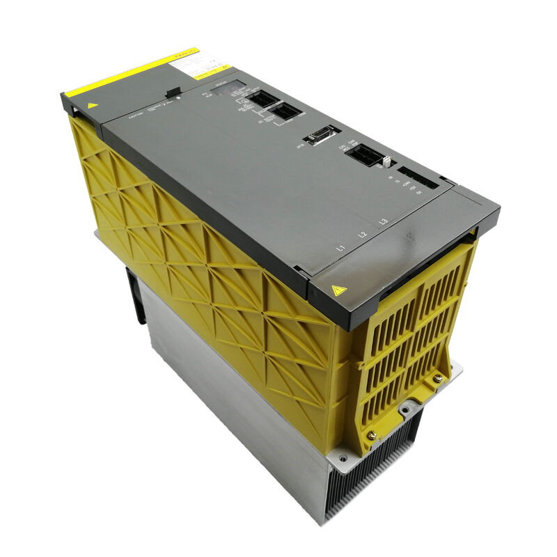
Fanuc A06B-6087-H145 | Alpha Power Supply Module PSM-45 — 55kW, 200–230V AC 3-Phase, 185A Input, 283–325V DC Bus, 165A Output, 300mm Module, External Forced Cooling
Overview
The Fanuc A06B-6087-H145 is the PSM-45, and it represents a clear step up from the rest of the A06B-6087 series in physical scale, power capacity, and installation requirements. Where the PSM-15 through PSM-37 share the same 150mm wide chassis and similar installation footprint, the PSM-45 uses a wider 300mm housing and weighs approximately 22kg — over twice the mass of the PSM-37.
This is not simply a case of more of the same; the PSM-45 belongs to a different physical class that brings with it different cabinet space requirements, different fastening and mounting considerations, and — critically — different cooling requirements.
The 55kW continuous output at 185A AC input places the PSM-45 in the power range appropriate for large machining centres with high-power spindle motors (15kW to 22kW class), multiple large-frame servo axes, or multi-spindle configurations where the total simultaneous power demand substantially exceeds what the PSM-37 can handle at 43kW. Aerospace machining centres with large-diameter cutters, heavy-duty turning centres for shaft and housing workpieces, and 5-axis machines with large pallet capacity all appear as typical PSM-45 installations.
The 165A DC bus output current is the figure that determines how many and how large the downstream SVM and SPM modules can be.
At 165A continuous, the PSM-45 can sustain the current demand of a large SPM spindle module at high spindle power simultaneously with multiple full-load SVM axis modules — a demand profile that would push the PSM-37's 43kW to or beyond its limit.
Unlike the PSM-15, PSM-26, and PSM-37, the PSM-45 requires external forced air cooling in addition to its own built-in fans.
This is the most critical installation distinction: a PSM-45 mounted in a cabinet without the required external duct arrangement and forced air supply will inevitably experience AL03 (heatsink over-temperature) shutdowns under production load conditions.
The external forced cooling requirement is not optional or environment-dependent — it is mandatory for the module to reach its rated continuous output at any ambient temperature.
Key Specifications
| Parameter |
Value |
| Module Designation |
PSM-45 |
| Rated Input Voltage |
200–230V AC, 3-phase |
| Rated Input Current |
185A at 200V |
| Rated Output Current |
165A |
| Input Frequency |
50/60Hz |
| Rated DC Bus Output |
283–325V DC |
| Rated Output Power |
55kW |
| Module Width |
300mm |
| Module Weight |
~22kg |
| Transistor Modules |
Three × 400A |
| Wiring Board |
A20B-2001-067x |
| Control Board |
A16B-2202-042x |
| Internal Fans |
Two × A90L-0001-0422 |
| Regeneration |
Active |
| External Cooling |
Required (forced air) |
| CNC |
Series 0-D, 15, 16i, 18i, 21i |
The 300mm Chassis — What the Size Means
The physical transition from the 150mm chassis of the PSM-15/26/37 to the 300mm chassis of the PSM-45 is an architectural boundary in the alpha drive system.
The 300mm width provides the heatsink surface area and board layout volume needed to handle the thermal and electrical demands at 185A input, 400A transistor modules, and 55kW continuous power.
The 22kg weight means the PSM-45 requires appropriate bracket support in the electrical cabinet — it cannot rely on the light clip mounting sufficient for smaller PSM modules.
The DC bus connection points on the PSM-45 are physically different from those on the 150mm chassis modules, and the cabinet layout must accommodate the larger module footprint.
Machine builders who specified the PSM-45 in the original design configured their electrical cabinets accordingly.
For retrofit or replacement purposes, a PSM-45 can only replace another PSM-45 (or its PSM-55 successor) — downsizing to a 150mm chassis PSM-37 is not mechanically possible, and even if it were, the 43kW limit would be insufficient for the load that required a PSM-45.
External Forced Cooling — Why It Is Non-Negotiable
The PSM-45's cooling architecture uses two internal fans to circulate air within the module housing and remove heat from the control electronics.
The external heatsink carries the thermal load from the three 400A transistor modules — this is where the bulk of the heat is generated. In the 150mm modules (PSM-15 through PSM-37), the external fan blowing across the heatsink fins is sufficient to reject this heat under rated load conditions.
In the PSM-45, the heat flux from the 400A transistors at 185A input is too large for a single external fan to reject — a ducted forced air supply to the heatsink is required.
In practice, this means the electrical cabinet must have a dedicated airflow path — typically a duct arrangement that brings cooler air from outside the cabinet directly to the PSM-45's heatsink inlet, or a separate external forced-cooling fan assembly mounted on the cabinet's exterior.
Machine builders who used the PSM-45 in original designs incorporated this cooling arrangement as a standard feature.
For a replacement PSM-45 fitted into a cabinet where the original external cooling has been modified, degraded, or compromised, ensuring the external forced cooling is fully functional before running the machine under production load is essential.
The two internal fans (A90L-0001-0422, the same type used in smaller PSM modules) are individually available as spare parts and can be replaced without exchanging the entire module.
400A Transistor Modules and Service Life
The three 400A transistor modules inside the PSM-45 operate at higher absolute current levels than in any smaller alpha PSM module.
While 400A transistors operating at a 185A continuous input level have significant electrical headroom, thermal cycling over years of production operation causes progressive degradation in transistor junction characteristics and solder joint integrity.
The eventual mode of failure for age-related transistor degradation is usually a gradual increase in saturation voltage, which increases switching losses and heat generation before the transistor eventually fails — often presenting initially as increased cabinet temperature rather than an immediate alarm.
The 400A transistors are available as individual spare parts, and replacement of a failed transistor module is a viable repair path.
The PSM-45's 22kg mass means that in-cabinet repair is impractical; the module must be removed from the cabinet for bench-level transistor replacement.
The wiring board (A20B-2001-067x) and control card (A16B-2202-042x) are not available separately — failed board conditions require unit exchange or specialist board repair.
PSM-45 and Its PSM-55 Successor
Fanuc's official documentation notes that the PSM-45 was superseded by the PSM-55 from August 1999.
In practice, both modules remain in active service across the global installed base — PSM-45 units fitted in machines built before 1999 continue to operate in production facilities, and aftermarket service support for the PSM-45 remains active.
The PSM-55 uses a different wiring board specification and delivers higher continuous power, but is physically compatible with the same cabinet mounting arrangement designed for the PSM-45 — making it the recommended upgrade path when a PSM-45 is being replaced and the opportunity to fit the higher-rated module is operationally beneficial.
FAQ
Q1: What specifically requires external forced cooling on the PSM-45 that the PSM-37 does not need?
The critical factor is heat flux density from the transistor modules. The PSM-45's three 400A transistors generate substantially more heat per unit of heatsink area than the smaller IGBT modules in the PSM-37 at rated load conditions.
The heatsink fin area available within the 300mm chassis, while larger than the 150mm chassis, still cannot reject the 400A transistors' heat output using only the external fan if the fan is operating against the hot air already present inside a loaded electrical cabinet.
The external forced air supply brings cooler air (not cabinet recirculated air) directly to the heatsink face, ensuring the heatsink runs at a predictably lower temperature.
Without this, the heatsink temperature margin above AL03 threshold narrows to the point where summer ambient temperatures or partial cabinet blockage produces AL03 shutdowns under production load.
Q2: Can the PSM-45 be directly replaced by the PSM-55 if the PSM-45 fails and only a PSM-55 is available?
Yes, the PSM-55 is the official successor to the PSM-45 and uses the same 300mm chassis format and the same cabinet mounting arrangement. The DC bus connection configuration is compatible.
The PSM-55 delivers higher continuous power than the PSM-45, which is safe for a system sized around the PSM-45 — the bus simply has more capacity than the downstream modules require.
The control card revision on the PSM-55 may differ slightly from the PSM-45, but no CNC parameter changes are required for this substitution, as the power supply module is transparent to the CNC's servo and spindle parameter configuration.
Q3: The PSM-45 weighs 22kg — what installation precautions does this weight require?
The 22kg mass requires that the module be mounted on bracket supports rated for this weight with appropriate safety factor.
Do not rely on a single screwed connection at the module's top for suspension — use the full mounting pattern specified in the Fanuc alpha series installation guide (B-65162). When removing and fitting the PSM-45 for replacement or servicing, use two-person handling or a trolley positioned to take the module weight as it slides out of the cabinet rack.
Dropping a 22kg module can damage the module body, the wiring boards, and any bus bar connections it contacts. When refitting, reconnect the DC bus bar connections before tightening the mounting fasteners to avoid bus bar stress at the connection points.
Q4: AL02 appears on the PSM-45 display — is this the internal fans or the external cooling system?
AL02 indicates a cooling fan fault — specifically one of the two internal fans (A90L-0001-0422) has stopped. The internal fans circulate air within the module housing and manage the control electronics' thermal environment.
AL02 does not directly indicate a failure in the external forced cooling duct arrangement; that failure path typically produces AL03 (heatsink over-temperature) rather than AL02. When AL02 appears, identify which of the two internal fans has stopped (listening for the running fan and the silent one), replace the failed fan, and verify operation before resuming production. If both internal fans are running and AL02 still appears, inspect the fan monitoring circuit on the control card.
Q5: What is the relationship between the PSM-45's 55kW rated power, 185A AC input, and 165A DC output — why are the input and output currents different?
The difference between 185A AC input and 165A DC output reflects the physics of AC-to-DC conversion.
The AC input to the PSM-45 is three-phase AC at 200–230V. After rectification, the DC bus operates at 283–325V. The power relationship P = V × I means that at 200V AC input with 185A (three-phase apparent current), the real power transferred after accounting for the three-phase factor and power factor is approximately 55kW.
The DC bus at 325V carrying 165A also delivers approximately 54kW (325V × 165A = 53.6kW).
The slight difference accounts for conversion losses — the rectifier, filter, and active switching circuits are not perfectly efficient, and a small fraction of the input power is dissipated as heat within the module itself.
The 165A output current rating is the relevant figure for sizing the downstream SVM and SPM modules' combined peak current demand against the module's DC bus capacity.

 Your message must be between 20-3,000 characters!