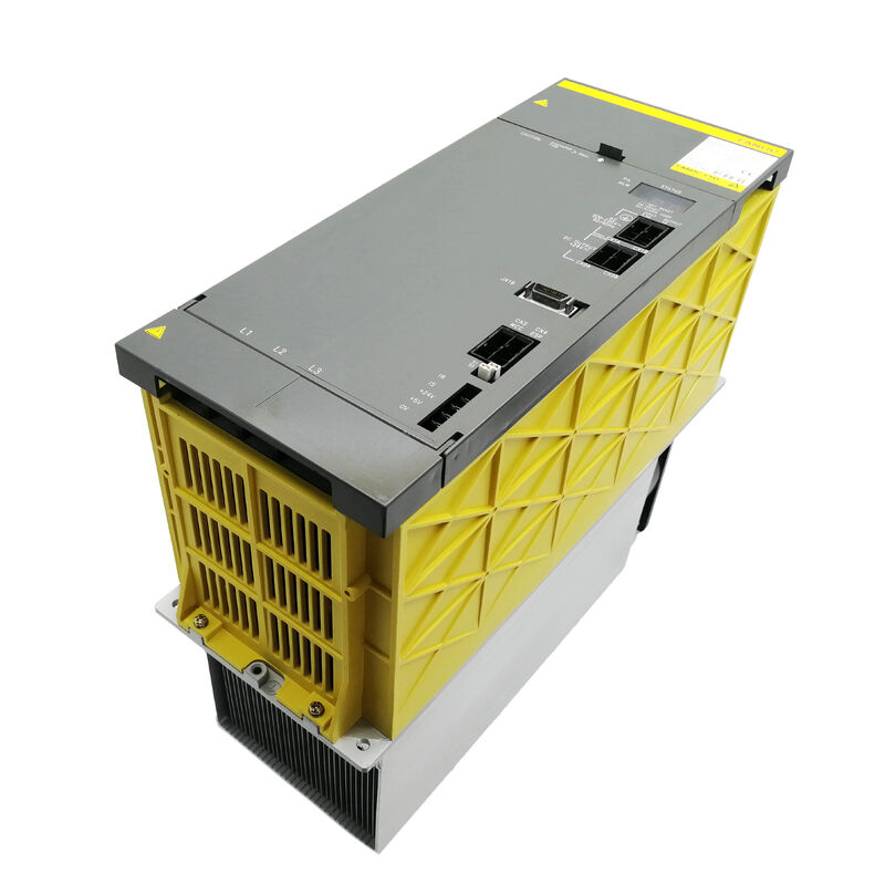
Fanuc A06B-6087-H115 | Alpha Power Supply Module PSM-15 — 17.5kW, 200–230V 3-Phase, 63A Input, 283–325V DC Bus Output, CNC 16i / 18i / 21i
Overview
The Fanuc A06B-6087-H115 is the PSM-15 — the 15-class power supply module in Fanuc's alpha series drive system. Its job is fundamental: it takes three-phase 200–230V AC from the facility power supply, rectifies and regulates it to a stable 283–325V DC bus, and distributes that bus voltage to all the servo and spindle amplifier modules in the drive rack. Every axis movement, every spindle rotation, every motor current pulse in an alpha series CNC machine ultimately draws its energy from this module's DC bus output. That makes the PSM-15 the single point of power continuity for the entire drive system — when it fails, the machine stops.
The 17.5kW continuous output rating defines the total combined continuous power demand that the PSM-15 can sustain across all its downstream drive modules simultaneously.
In a typical mid-size machining centre configuration, a PSM-15 serves a spindle amplifier module (SPM) and a combination of servo amplifier modules (SVM), powering the spindle and feed axes together within this 17.5kW envelope.
The 63A rated input at 200V reflects the primary AC draw under full output conditions, and this figure is what the facility electrical design must accommodate — both in terms of breaker rating and power line impedance.
What distinguishes the PSM-15 from the simpler PSMR (regenerative resistor) power supply variants in the same family is its active power regeneration capability. When a servo or spindle motor decelerates, the kinetic energy stored in the rotating mass flows back through the amplifier toward the DC bus.
n a PSMR system, this energy is dissipated in a resistor as heat. In the PSM-15, an active front-end circuit returns this regenerated energy to the three-phase AC supply — effectively feeding the energy back into the facility electrical system rather than burning it as heat.
For machines with high spindle inertia or frequent heavy decelerations, this regeneration capability meaningfully reduces heat generation inside the electrical cabinet and improves the overall energy efficiency of the drive system.
The PSM-15 is a 150mm wide module — wider than the 60mm to 90mm SVM servo modules it powers — and carries both internal and external cooling fans plus an external heatsink finned block.
This thermal management arrangement reflects the continuous high-current operation the PSM-15 sustains: the 200A transistor modules at its core generate substantial heat that must be continuously extracted to maintain component temperatures within rated limits.
The external fan (A90L-0001-0335/B) and internal fan (A90L-0001-0422) are individually available as spare parts, which is meaningful because a fan failure is a recoverable maintenance event rather than a cause for complete module replacement.
Key Specifications
| Parameter |
Value |
| Module Designation |
PSM-15 |
| Rated Input Voltage |
200–230V AC |
| Rated Input Current |
63A at 200V |
| Input Phase |
3-phase |
| Input Frequency |
50Hz / 60Hz |
| Rated Output Voltage |
283–325V DC |
| Rated Output Power |
17.5kW |
| Transistor Modules |
Three 200A |
| Width |
150mm |
| Wiring Board |
A20B-1006-0470 |
| Control Card |
A16B-2202-042x |
| Regeneration |
Active (power-returned to AC supply) |
| External Fan |
A90L-0001-0335/B |
| Internal Fan |
A90L-0001-0422 |
| AC Reactor (recommended) |
A81L-0001-0123 |
The DC Bus — What It Means to Power Every Axis
The 283–325V DC bus that the PSM-15 maintains is not just a power rail — it is the energy reservoir from which all instantaneous motor current demands are drawn. When three servo axes simultaneously accelerate, all three pull current from the DC bus simultaneously.
The PSM-15's front-end rectifier and filter capacitor bank are sized to sustain the peak transient demands of the downstream amplifiers while holding the bus voltage within the 283–325V regulated range.
If the combined peak current demand exceeds what the capacitor bank can transiently supply, the bus voltage sags and the CNC detects the under-voltage condition as a drive alarm.
This is why PSM selection for a specific machine must consider not just the continuous power demand but the peak simultaneous current profile of all connected axes.
The 15kW nominal designation corresponds to a continuous rating; the actual PSM-15 hardware supports higher peak currents for the short durations characteristic of servo acceleration events.
Fanuc's PSM selection procedure accounts for this by applying a simultaneous operation factor to the sum of all axis power ratings — the PSM-15 at 17.5kW continuous is typically appropriate for systems whose peak simultaneous demand falls within the selection guideline.
Power Regeneration — Energy and Heat
On a machine without active regeneration, spindle deceleration from rated speed to zero represents a significant energy disposal problem.
A 7.5kW or 11kW spindle motor spinning at 6000rpm stores substantial rotational kinetic energy. Bringing it to a stop in a tool change cycle of 2–3 seconds requires absorbing all that kinetic energy somewhere — in a PSMR system, into a resistor; in a PSM system, back into the AC grid.
The PSM-15's active regeneration circuit continuously monitors the DC bus voltage and, when deceleration energy causes the bus to rise toward its upper limit, switches the active front end to return current to the three-phase supply.
This keeps the DC bus within regulation limits without a thermal dissipation event, eliminates the need for a separate regenerative resistor assembly, and reduces the heat load inside the electrical cabinet.
Over a full production shift on a machine with frequent tool changes and spindle acceleration/deceleration cycles, the thermal benefit inside the cabinet is substantial — cabinet temperatures run lower, component life extends, and the need for cabinet air conditioning capacity may be reduced.
Cooling System and Fan Maintenance
The PSM-15's thermal management uses three parallel paths: the external heatsink finned block conducts heat from the transistor modules to the exterior air; the external fan (mounted on the outside of the module) draws ambient air through the heatsink fins; and the internal fan circulates air within the module housing to prevent hot spots on the control electronics.
All three paths must be operational for the module to sustain rated output continuously.
Fan maintenance is the most common preventive action for PSM-15 longevity. Both fans are available as separate spare parts and can be replaced without exchanging the entire module.
The alarm code AL02 on the PSM-15's front panel 7-segment display indicates that the internal control circuit fan has stopped — this is a warning before a thermal over-temperature condition, and should be treated as an urgent maintenance event rather than a deferred repair.
The external fan's failure path is similar: heatsink temperature rises until AL03 (heatsink over-temperature) triggers a drive shutdown.
A practical recommendation for facilities operating alpha series machines is to record the alarm history and replace both fans during any scheduled machine maintenance stop, regardless of whether either fan has failed, if the module is known to be more than five years old in continuous production service.
Fan bearing wear is age-dependent and does not always present obvious noise before bearing failure.
Internal Boards and Serviceable Components
The PSM-15 contains two primary boards: the wiring board A20B-1006-0470 handles the power section connections, gate drive signals to the transistor modules, and I/O interface; the control card A16B-2202-042x (suffix varies by revision) runs the regulation algorithm, protection logic, and the LED alarm display.
Neither board is sold separately — the module is the service unit.
The transistor modules (three 200A units), the internal fan, the external fan, the battery pack for the control circuit, and the DC bus fuses are available as individual spare parts and can be replaced by qualified service engineers during an overhaul.
Alpha PSM-15 Alarm Code Reference
The PSM-15's front panel 7-segment LED display shows alarm codes during fault conditions. Key alarm meanings specific to the PSM-15:
AL01 — Overcurrent in the main circuit input (specific to PSM-15 through PSM-30 class; differs from PSM-5.5 and PSM-11 where AL01 indicates IPM fault). Check three-phase supply voltage balance, incoming line fuses, and the AC reactor condition.
AL02 — Control circuit cooling fan stopped. Replace the internal fan before resuming operation.
AL03 — Main circuit heatsink over-temperature. Check external fan operation, verify cabinet ambient temperature is within specification, and confirm the heatsink fins are not blocked with coolant mist or swarf deposits.
AL04 — DC link voltage drop. Indicates the DC bus has fallen below the minimum operating threshold. May indicate a power supply input problem, a failed rectifier section within the PSM, or excessive simultaneous current demand from downstream modules.
AL07 — Low-voltage DC (DC link charge circuit fault at startup). The DC bus pre-charge circuit has failed to raise the bus to operating voltage within the expected time — often indicates a failed pre-charge resistor or contactor within the PSM.
FAQ
Q1: Can the A06B-6087-H115 power both alpha and alpha i series amplifier modules in the same drive rack?
The A06B-6087 PSM family is the power supply generation aligned with the alpha (pre-i) amplifier modules — specifically the A06B-6079, A06B-6080, A06B-6088, A06B-6089, and A06B-6096 SVM and SPM families.
The alpha i (ai) generation amplifiers (A06B-6114 series SVM) use the A06B-6110 series aiPS power supplies.
These two power supply generations are not cross-compatible within the same drive bus.
A machine undergoing a partial drive system upgrade from alpha to alpha i would require replacing the PSM as well as the SVM and SPM modules to maintain a compatible power bus architecture.
Q2: What is the purpose of the recommended AC reactor (A81L-0001-0123) at the PSM-15 input?
The AC reactor (also called a line reactor) is installed between the facility power supply and the PSM-15's three-phase input terminals.
It serves two purposes: it limits the rate of current rise during the DC bus pre-charge phase at startup, reducing the inrush current stress on the PSM's rectifier diodes and the facility power line; and it attenuates harmonic distortion that the PSM's rectifier circuit would otherwise inject back into the facility power system.
In facilities with strict power quality requirements or where the PSM shares a power feed with sensitive equipment, the reactor is not optional — it is a protection for both the drive system and the facility electrical infrastructure.
Q3: When the PSM-15 shows AL01, should the entire module be replaced or can the fault be diagnosed more specifically?
For the PSM-15 class, AL01 indicates overcurrent in the main circuit input — the three-phase AC current flowing into the rectifier section has exceeded the protection threshold. Before concluding the PSM's internal rectifier or transistor modules have failed, check: the three-phase supply voltage at the PSM input terminals (voltage imbalance or supply sag can cause apparent overcurrent), the incoming line fuses, the AC reactor if fitted (an open-phase condition in the reactor produces severe supply imbalance), and whether the alarm correlates with a specific operational event (spindle start, simultaneous multi-axis acceleration).
A fault that only appears under heavy load may indicate a marginal transistor module, while a fault that appears immediately at power-on points to a rectifier or pre-charge circuit problem.
Q4: How is the 17.5kW output rating used to size the PSM-15 for a specific machine configuration?
The PSM-15's 17.5kW is a continuous rating — the total power the module can deliver to all connected SVM and SPM modules simultaneously without exceeding thermal limits.
To verify the PSM-15 is adequate for a given machine, sum the rated continuous power of all connected amplifier modules (servo + spindle), apply a simultaneous operation factor (typically 0.7 to account for the fact that all axes rarely demand full rated power simultaneously), and confirm this figure is below 17.5kW.
Additionally, verify the peak current demand of the spindle amplifier's motor at startup or during heavy cutting does not exceed the PSM's peak current capability for the duration of the event.
Q5: What is the effect on the machine if either the internal or external fan in the PSM-15 fails, and how urgent is the repair?
A fan failure should be treated as urgent — not because the machine stops immediately, but because the remaining thermal margin shrinks and the timeline to a heat-related shutdown becomes unpredictable.
With the external fan stopped, the heatsink temperature rises during operation until AL03 triggers and the PSM shuts down to protect the transistor modules.
In a cool ambient environment this might take minutes or hours; in a summer production environment with a hot cabinet, it can happen within minutes of the fan stopping. Internal fan failure carries similar consequences for the control board temperature.
In either case, continue operating the machine only with close monitoring and plan for immediate fan replacement — fan replacement is a minor repair compared to the transistor module replacement that overheating failure would necessitate.

 Your message must be between 20-3,000 characters!