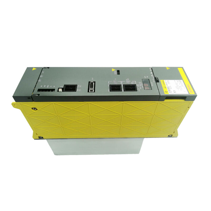
Fanuc A06B-6077-H111 | Alpha Power Supply Module PSM-11 — Field Service & Maintenance Reference, 13.2kW, 200–230V, 49A, Legacy Alpha Drive Systems
Overview
The Fanuc A06B-6077-H111 is a 13.2kW alpha series power supply module found on thousands of compact CNC machine tools worldwide. It sits behind decades of milling machines, lathes, drilling centres, and special-purpose equipment controlled by Series 0-C, 0-D, 16, 18, and 21 CNCs.
Many of those machines are now in the fifteen-to-thirty-year bracket of service life — old enough that their PSM-11 has likely never been opened, cleaned, or had its fan replaced. That profile — old machine, original power supply, unknown service history — is the context in which most PSM-11 maintenance situations actually occur, and it is the perspective this article is written from.
Understanding how the PSM-11 fails, what the alarm codes actually mean on this specific module versus larger PSM variants, and how to make the repair-vs-exchange decision confidently is more useful to a maintenance team running aging alpha systems than another description of the module's AC-to-DC conversion principle.
Key Specifications
| Parameter |
Value |
| Input Voltage |
200–230V AC, 3-phase |
| Input Current |
49A at 200V |
| DC Bus Output |
283–325V DC |
| Output Power |
13.2kW |
| Wiring Board |
A16B-2202-0461 |
| Control PCB |
A16B-2202-0420 |
| Fan |
A90L-0001-0422 |
| Regeneration |
Active (no external resistor required) |
| External Cooling |
Forced air — mandatory |
| CNC |
0-C/D, 16, 18, 21, 0i-A |
AL01 on the PSM-11 — This Is Not the Same as AL01 on the PSM-15
This is worth stating plainly because it causes diagnostic errors in the field. On the PSM-11 (and PSM-5.5), AL01 means the IPM (Intelligent Power Module) has detected an internal fault.
On the PSM-15 and all larger A06B-6087 modules, AL01 means overcurrent in the AC input. Same alarm number, categorically different root cause, different diagnosis path.
When AL01 appears on a PSM-11:
It does not necessarily mean the AC supply has a problem.
The IPM fault on the PSM-11 indicates the power transistor module has triggered its internal protection — typically due to overcurrent through the output stage, overtemperature in the transistor junction, or an actual transistor failure. Before concluding the IPM has failed, go through the following:
- Disconnect all SVM and SPM modules from the DC bus bar and attempt to power the PSM-11 alone. If AL01 clears with nothing connected, the fault is in a downstream amplifier (motor short, winding insulation failure, or amplifier transistor fault) drawing excessive current from the bus.
- If AL01 remains with the bus completely unloaded, the IPM inside the PSM-11 has either tripped thermally (insufficient external cooling) or has genuinely failed electrically.
- Check the external cooling arrangement before condemning the IPM.
- A blocked duct, a failed external fan, or a cabinet running hot in summer can cause the IPM to trip its thermal protection and display AL01 without any transistor damage. Restoring adequate cooling may clear the alarm without further intervention.
- If the external cooling is confirmed adequate and AL01 persists with no load on the bus, the IPM module requires replacement or the unit requires exchange.
AL02 — Fan Failure: The Most Preventable Cause of Escalating Damage
AL02 indicates the internal control circuit fan (A90L-0001-0422) has stopped. On the PSM-11, this fan circulates air within the module housing to keep the control PCB and wiring board at safe operating temperatures.
It is a small brushless fan that runs continuously whenever the module is powered. Over years of operation, the bearing in this fan gradually wears.
The bearing noise may become audible — a faint rattling or roughness at startup — before the bearing seizes. But in a noisy machining environment, this early warning is rarely noticed.
When the fan bearing seizes, the fan stops.
AL02 appears. If the alarm is responded to quickly and the fan replaced (A90L-0001-0422 is a standard spare), the story ends there. If the alarm is dismissed or the machine is pushed through production with the fan stopped, the control PCB temperature climbs.
At elevated temperatures, electrolytic capacitors on the control board experience accelerated degradation, solder joints can develop micro-cracks from thermal stress, and eventually a board component fails. What started as a $50–100 fan replacement has turned into a board-level repair or full unit exchange.
Fan replacement is the single highest-ROI maintenance action on the PSM-11. A replacement fan costs a fraction of the module's exchange value.
On any PSM-11 that is known to be more than five years old in continuous production service, replacing the fan proactively during a scheduled maintenance stop is sound engineering practice regardless of whether AL02 has appeared.
The fan's rated service life at continuous operation has a ceiling; planning its replacement beats having it fail unannounced during a production run.
AL05 — Pre-Charge Failure: What Actually Goes Wrong
AL05 means the DC bus capacitors did not reach operating voltage within the expected pre-charge time after power-on.
The pre-charge circuit charges the bus capacitors through a current-limiting resistor during the first seconds after power is applied, before the main contactor closes and the bus goes live.
If voltage does not reach threshold in time, AL05 trips.
Common causes on an aging PSM-11:
Pre-charge resistor degradation. The pre-charge resistor inside the module limits inrush current during capacitor charge-up. Over thousands of power-on cycles, this component can drift in resistance value or develop intermittent open-circuit conditions.
A resistor that has increased in value slows the pre-charge rate; if the increase is large enough, the capacitors cannot reach operating voltage before the time-out.
Main circuit capacitor deterioration. Electrolytic capacitors on the DC bus have a finite service life, particularly when operated in environments with elevated temperatures.
As capacitors age, their equivalent series resistance (ESR) increases, which affects charge rate and efficiency.
An extreme case where one or more capacitors has become high-ESR can prevent the pre-charge from completing correctly.
Main contactor issues. In some configurations, the pre-charge sequence involves a contactor switching.
A contactor that is sticking or failing to close at the correct moment can also produce AL05 patterns.
AL05 that appears consistently at every power-on (not intermittently) and in a machine that is many years old points to component wear.
AL05 that appears intermittently — sometimes clearing on a second power attempt — is more characteristic of a contactor or timing issue.
AL04 — DC Link Voltage Drop: Bus vs. Supply
AL04 indicates the DC bus voltage has fallen below the operating threshold. The diagnosis path splits into two directions:
Supply-side: The three-phase AC input to the PSM-11 is insufficient to maintain bus voltage under load.
Check: voltage at the PSM-11 input terminals (not just at the supply panel — voltage drop along the cable under load matters at 49A), balanced voltage across all three phases, and input fuse integrity.
A blown fuse on one phase causes a two-phase supply condition that cannot sustain 13.2kW output — the bus sags and AL04 appears.
Load-side: A downstream SVM or SPM module is drawing excessive current from the bus, pulling the voltage below the regulation range. This can occur with a motor that has developed a winding fault creating a higher-than-normal current draw, or with an amplifier transistor that has partially failed and is drawing disproportionate quiescent current. Disconnecting amplifiers one by one while monitoring bus voltage helps isolate this pattern.
The Tandem Alarm Pattern — When SPM and PSM Alarm Together
A diagnostically important characteristic of the PSM-11 system is that certain PSM faults trigger simultaneous alarms on the connected spindle amplifier module (SPM). Knowing these tandem patterns prevents misdiagnosis:
- AL02 on PSM-11 + Alarm 59 on SPM: The PSM fan stopped. The SPM is reacting to PSM condition, not failing independently. Fix: replace PSM-11 fan.
- AL04 on PSM-11 + Alarm 33 on SPM: DC link pre-charge failure. The SPM is reporting a PSM-originated problem.
- High DC bus voltage (pre-AL07) + Alarm 11 on SPM: DC bus overvoltage, potentially PSM-related.
In all these cases, investigating only the SPM alarm and ignoring the PSM display will lead to wrong conclusions. Always read both the PSM-11's front panel display and the CNC alarm screen together.
Repair vs Exchange — Making the Right Call
The PSM-11's two main circuit boards — wiring board A16B-2202-0461 and control PCB A16B-2202-0420 — are not available as standalone spare parts. If either board has failed and the fault cannot be resolved at the component level, the module requires either whole-unit exchange or specialist board repair from a company that stocks individual components for these boards.
Exchange makes sense when:
- The machine is in urgent production and downtime cost per hour is high.
- The fault is in the board, and component-level repair is not locally available.
- The module is old enough that an overhaul-grade exchange (cleaned, full inspection, new fan, key components replaced) provides a service life extension that approaches or equals the production life remaining for the machine.
Board-level repair makes sense when:
- The fault has been identified at a component level (a specific capacitor, a driver transistor, a reference IC) by a qualified technician with the right test equipment.
- The machine is not urgently down, allowing time for send-away repair.
- The machine itself has significant remaining production life and cost management of spares matters.
The fan and fuses are always worth replacing before condemning the module — these are the lowest-cost service interventions and they resolve a meaningful fraction of PSM-11 service events on aging machines.
Legacy Machine Context: 0-C and 0-D Era Alpha Systems
The Series 0-C and 0-D controls were Fanuc's mainstream CNC platforms through the late 1980s and 1990s.
A large number of small machining centres, drilling centres, and turning centres worldwide were built around these controls with alpha drive systems — and many are still running.
The PSM-11 is the power supply module that was sized for the smaller configurations in this machine generation.
These machines are now typically between 20 and 35 years old. That age profile means the PSM-11 in a 0-D machine may have accumulated tens of millions of operating hours without any component-level service. The electrolytic capacitors in the bus filter section have been cooking at some fraction of their rated life since installation.
The control board's components have cycled through thermal expansion and contraction for decades.
The fan bearing has been spinning continuously across every shift the machine has run.
None of this means the PSM-11 is about to fail — Fanuc's hardware was built conservatively and age-related failures on these modules often present gradually rather than catastrophically.
But it does mean that a PSM-11 in a vintage 0-D machine that has never been serviced is a candidate for proactive maintenance: fan replacement at minimum, and a visual inspection of the electrolytic capacitors for bulging tops or leaked electrolyte, which are visible signs of capacitor end-of-life.
FAQ
Q1: AL01 just appeared on the PSM-11. The machine was running normally and then tripped. The three-phase supply checks out fine. What failed?
On the PSM-11, AL01 means the IPM (not AC overcurrent, which is the AL01 meaning on larger PSM-15+ modules). Immediately check the external cooling arrangement — if the heatsink fan or external cooling duct has failed, the IPM may have tripped its thermal protection without actually failing electrically. Restore cooling and attempt a restart.
If AL01 clears, the IPM is intact but was thermally stressed.
If AL01 persists with the bus completely unloaded and cooling restored, the IPM has failed and the unit requires exchange or transistor module replacement.
Q2: The machine trips AL05 occasionally at power-on but sometimes starts normally on a second attempt. Is this the pre-charge resistor or the capacitors?
Intermittent AL05 — where the machine sometimes starts on a second attempt — points more toward a timing or contactor issue than a fully failed component. If the pre-charge resistor were severely degraded or a capacitor were truly open, the fault would be consistent.
An intermittent fault that resolves on retry suggests either a marginal pre-charge resistor that is just at the edge of the timing threshold (which gets worse with age and temperature), or a main contactor making intermittent contact.
Monitoring the pre-charge sequence with a DC voltmeter on the bus during startup attempts can help determine whether the bus is charging slowly (resistor issue) or not charging at all on the failed attempts (contactor or resistor open circuit).
Q3: Can the fan (A90L-0001-0422) be replaced while the module is in the machine, or does it require removal?
The fan can typically be accessed and replaced without removing the entire PSM-11 from the cabinet, depending on the cabinet layout — the fan is mounted in an accessible position on the module housing.
Power down the machine completely and lock out the supply before working near the PSM-11, even though the fan itself is low-voltage. After fitting the new fan, verify it spins in the correct direction and that the replacement fan's airflow direction matches the original.
An incorrectly oriented fan reduces airflow effectiveness or in some positions could draw warm air into the module rather than expelling it.
Q4: A machine running a Series 21 control shows simultaneous alarms on the PSM-11 (AL02) and SPM (Alarm 59). Both alarms appeared at the same time. Which module failed?
This tandem alarm pattern — AL02 on PSM combined with Alarm 59 on the SPM — is characteristic of the PSM fan stopping.
The SPM is reacting to the PSM condition, not failing independently. The SPM itself is almost certainly functional.
Replace the PSM-11's internal fan (A90L-0001-0422), clear alarms, and restart.
The SPM alarm should not return. If the SPM alarm returns after the PSM fan is confirmed running, then the SPM warrants separate investigation — but the fan is the overwhelmingly likely cause when both alarms appear simultaneously at first presentation.
Q5: The PSM-11 in a 25-year-old machine is running without alarms, but the machine is due for a major overhaul. What PSM-11 service is worth doing during the overhaul?
During a major overhaul on a vintage machine, the PSM-11 service that pays back reliably is: fan replacement (A90L-0001-0422) as a guaranteed preventive action; visual inspection of the electrolytic capacitors on both the main bus and control board for bulging tops, leaked electrolyte residue, or swollen cases; cleaning of the external heatsink fins with compressed air to remove machining swarf and dust accumulation; and testing of the pre-charge sequence and bus voltage stability after power-on.
If any capacitors show physical signs of degradation, or if the bus voltage measurement shows excessive ripple during loaded operation (which requires a calibrated oscilloscope), board-level repair with capacitor replacement is the appropriate intervention.
A module that passes visual inspection and functional test after fan replacement and heatsink cleaning is likely good for another significant service interval.

 Your message must be between 20-3,000 characters!