Fanuc A06B-6079-H206 | Alpha Servo Amplifier Module — SVM2-40/40, Dual-Axis, Type A, 283–325V / 5.3kW, 12.5A / 230V per Axis
Overview
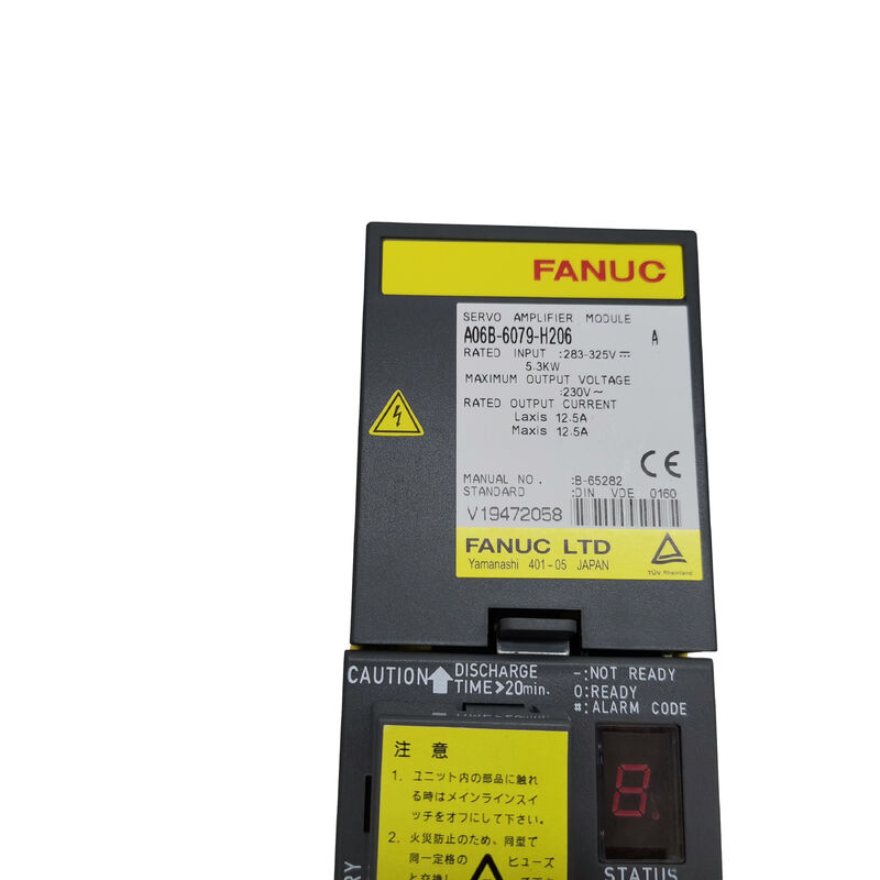
The Fanuc A06B-6079-H206 is the SVM2-40/40, a dual-axis alpha servo amplifier module delivering 12.5A rated continuous output on each of its L and M channels from a 5.3kW / 283–325V DC bus input.
Within the A06B-6079 alpha module family, the SVM2-40/40 occupies a practical middle ground: it provides 12.5A per axis — the same current rating as the single-axis SVM1-40L — but delivers this to two independent channels from one module, reducing cabinet rail consumption and the number of DC bus connection points compared to running two separate SVM1 units.
The Type A PWM interface marks this module as part of Fanuc's established first-generation alpha series, designed to communicate with the series 0M, OT, 15A, 16A, 18A, and 21A CNC controls that were the industry standard during the alpha system's active production years.
This CNC generation remains installed on a significant number of machine tools worldwide — the Fortune VT-26 vertical lathe and the Toshiba VTL TUE-20 large vertical turning centre are documented examples where the A06B-6079-H206 serves as the primary axis drive module.
The motor compatibility list — α3/3000, α6/2000, and α12/2000 in any combination across the L and M channels — covers the mid-range of Fanuc's alpha servo motor family.
Both channels can drive the same motor class, or the two channels can drive different motor models from this range without any conflict in the module's current regulation.
The module handles asymmetric load conditions between L and M channels automatically, regulating each channel's current independently.
An important ordering detail: the A06B-6079-H206 may be fitted with one or two CX5 absolute encoder battery connection ports depending on the machine configuration.
When sourcing a replacement, specifying the required CX5 port count ensures the replacement unit matches the machine's wiring and absolute position battery arrangement exactly.
Key Specifications
| Parameter |
Value |
| Module Model |
SVM2-40/40 |
| Axes |
2 (L and M channels) |
| Rated Input |
283–325V DC bus, 5.3kW |
| Max Output Voltage |
230V AC |
| Output Current (L/M) |
12.5A rated each |
| Interface |
PWM Type A |
| Compatible Motors |
α3/3000, α6/2000, α12/2000 |
| Wiring Board |
A16B-2203-0592 |
| Control Card |
A20B-2001-0931 |
| Manual |
B-65162 |
| Compatible Controls |
FANUC 0M/OT/15/16/18/21 |
12.5A Per Axis — Motor Class and Application Context
At 12.5A continuous per channel, the SVM2-40/40 is sized for Fanuc's mid-heavy alpha motors.
The α12/2000 motor — 12N·m continuous torque at 2000rpm — is the most demanding motor that comfortably stays within the 12.5A envelope at rated full-load torque.
Below it, the α6/2000 (6N·m, 2000rpm) and α3/3000 (3N·m, 3000rpm) operate well within the current ceiling, leaving substantial headroom for acceleration transients.
On vertical turning centres, this motor class typically appears on the main X and Z axes — the carriage drives that control tool position relative to the workpiece on machines cutting large-diameter components.
The SVM2-40/40's dual-channel format handles both axes simultaneously from a single module, which is operationally significant during continuous contouring cuts where X and Z motion occur simultaneously throughout the cutting path.
Type A Interface — Configuration and CNC Compatibility
The Type A PWM interface uses S1 jumper settings on the wiring board to configure the interface parameters.
Incorrect S1 settings produce VRDY OFF alarms or high-current alarms on power-up — the standard symptoms of an interface configuration mismatch between the module and the CNC.
When fitting a replacement H206, the S1 jumper settings from the original module must be replicated on the replacement.
These settings determine the axis address and interface mode for each channel.
The Type A interface is used with FANUC Series 0-C, 15A, 16A, 18A, and 21A controls — the A-suffix CNC generation.
For machines with B-suffix controls (0-MD, 16B, 18B, 21B), the equivalent module is from the A06B-6080 series, which carries Type B interface hardware while maintaining the same SVM2-40/40 electrical ratings.
FAQ
Q1: The wiring board is listed as both A16B-2203-0592 and A16B-2202-0772 — which is correct for my machine?
Both are legitimate wiring board variants for the SVM2-40/40.
The A16B-2202-0772 is the earlier revision; A16B-2203-0592 is the later revision, which incorporates minor PCB improvements. Both are fully compatible with the same motors and CNC controls.
When ordering a replacement H206, the service provider will supply the currently available wiring board revision. Unless your machine documentation specifically requires the earlier revision, either board is acceptable for a direct replacement.
Q2: What is the CX5 absolute encoder battery port, and why does the count matter?
CX5 connectors on the wiring board carry the lithium battery supply that maintains absolute pulse coder position data during machine power-off.
A machine with one axis using absolute feedback has one CX5 port; a machine with two absolute-feedback axes has two CX5 ports.
The battery count on the replacement module must match the original — fitting a one-CX5 replacement in a machine expecting two connections leaves one axis without absolute backup, causing reference position loss on power cycle and a BAT alarm on the CNC.
Q3: The A06B-6079-H206 is listed for 0M, OT, 15, 16, 18, and 21 series — which specific series variants are compatible?
Type A interface modules are compatible with the A-suffix variants: Series 0M, OT, 15A, 15B, 16A, 18A, and 21A/TA.
The B-suffix series (0-MD, 16B, 18B, 21B) uses Type B PWM interface and requires the A06B-6080 series SVM2-40/40.
The documented typical controls for this specific module are 16TA, 16MA, 18TC, 18MC, 21TB, and 21MB — note that 21TB/21MB are Type B CNC variants, so verify the machine's CNC interface type from the machine builder's electrical documentation before ordering.
Q4: What alarm codes indicate a fault in the A06B-6079-H206?
Alarm 8 (L-axis overcurrent, HCL) and Alarm 9 (M-axis overcurrent, HCM) are the most common sudden fault alarms, almost always caused by motor winding insulation breakdown rather than module failure.
Disconnect the affected motor's U/V/W cables and test insulation resistance to protective earth — several hundred megaohms or higher is acceptable.
If the alarm clears with cables disconnected, the motor or cable is the fault source. Alarm 8. (dot-suffix) or 9. indicates an L or M axis IPM transistor alarm, which does suggest a module output stage fault. Combined alarms (b, C, d, E) indicate simultaneous multi-channel faults.
Q5: Can the SVM2-40/40 replace the SVM2-40/80 (A06B-6079-H207) if the machine normally has asymmetric axis current requirements?
Only if both axes draw 12.5A or less. The SVM2-40/80 provides 12.5A on L and 18.7A on M — used when the M-axis motor requires the higher 18.7A class.
Substituting the SVM2-40/40 (both channels at 12.5A) on a machine where the M axis uses an α22-class motor that draws up to 18.7A will produce M-axis overcurrent alarms under full machining load.
If the M-axis motor is in the α6/α12 class (within 12.5A), the substitution is electrically safe provided servo parameters are correctly set.


 Your message must be between 20-3,000 characters!