FANUC A06B-6058-H005 | S Series Single-Axis AC Servo Amplifier — 3.08 kW, 10S/20M, PWM Interface, Japan Origin
Part Number: A06B-6058-H005
Manufacturer: FANUC Corporation (Japan)
Product Type: Single-Axis AC Servo Amplifier Unit
Product Series: A06B-6058 (S Series)
Motor Compatibility: FANUC 10S, 20M / 20S-1500
Power Rating: 3.08 kW
Interface: PWM (digital)
Frame: Open (yellow aluminium heatsink construction)
Control Board: A20B-1003-0090
Power Board: A20B-1003-0081
Overview
The A06B-6058-H005 is a single-axis AC servo amplifier from FANUC's S series — one of the most significant servo drive platforms in FANUC's history. It powers 10S and 20M AC servo motors at a rated output of 3.08 kW, making it the appropriate drive for medium-duty axis motion in the CNC machine tools of its era.
The unit communicates with the CNC controller via PWM digital interface, placing it firmly in FANUC's digital servo generation that replaced the earlier analogue drive systems.
The S series drives were paired with FANUC's System 10, 11, 12, and 15 controllers and with the 0-series controllers in various configurations.
These drives and controllers powered a generation of machining centres, turning centres, and multi-axis production machines that are still in productive operation around the world.
The A06B-6058-H005 is the drive unit that keeps a specific set of those machines running.
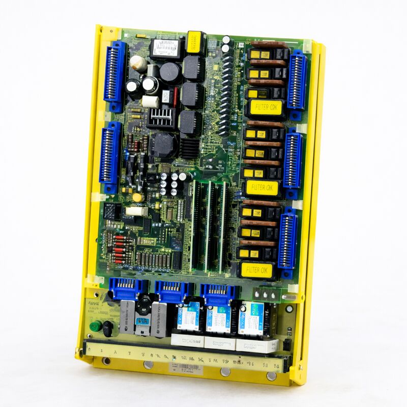
Physically, the drive uses FANUC's characteristic open yellow-frame construction: the electronics and power components are mounted around an aluminium heatsink, open to the cabinet airflow. This design is efficient and durable.
It allows inspection of the drive's components without disassembly, and the construction is mechanically robust enough to operate reliably through years of continuous production use.
Key Specifications
| Parameter |
Value |
| Part Number |
A06B-6058-H005 |
| Manufacturer |
FANUC Corporation |
| Product Type |
Single-Axis AC Servo Amplifier |
| Series |
S Series (A06B-6058) |
| Power Rating |
3.08 kW |
| Compatible Motors |
FANUC 10S, 20M, 20S-1500 |
| Drive Interface |
PWM (digital) |
| Frame |
Open (yellow frame, aluminium heatsink) |
| Control Board |
A20B-1003-0090 |
| Power Board |
A20B-1003-0081 |
| Operating Temperature |
0 – 40°C |
| Max. Altitude |
1,000 m above sea level |
| Max. Vibration |
5G |
| Condition Available |
New (surplus) / Refurbished / Tested exchange |
PWM Digital Interface — The S Series Architecture
The A06B-6058-H005 uses a PWM (pulse-width modulation) interface to receive velocity commands from the CNC controller. This is a digital interface — the drive doesn't receive an analogue voltage representing the desired speed, it receives a digital PWM signal encoding the velocity command. This approach was a significant step forward from the analogue drives of the previous generation.
PWM interface drives offered better noise immunity than analogue counterparts.
The digital signal was less susceptible to interference from the power cables, motor cables, and electrical switching events that fill a CNC machine cabinet.
The result was more consistent velocity control and less tendency for drives to pick up noise as unwanted velocity disturbances.
The drive processes this PWM input, generates the gate drive signals for its IGBT power transistors, and delivers the resulting AC current to the connected servo motor.
The motor's encoder feedback completes the velocity control loop: the encoder signals go back to the controller, which compares commanded and actual velocity and adjusts the PWM output accordingly. The S series drive executes this loop reliably at the current levels its 3.08 kW rating defines.
Internal Board Structure
The A06B-6058-H005 is a complete servo amplifier unit. Inside the open frame, two boards share the workload. The control board — A20B-1003-0090 — handles the drive's electronics: the PWM input processing, the current control, the protection logic, and the drive's operational status monitoring. The power board — A20B-1003-0081 — contains the power transistors and gate drive circuits that handle the high-current output to the motor.
These boards can be replaced independently when required.
A control board fault produces control-related alarms and abnormal operational behaviour without necessarily damaging the power board.
A power board fault — typically from a failed transistor — produces overcurrent or short circuit alarms and may leave the control board intact.
This separation makes targeted component-level repair practical rather than requiring complete unit replacement for every fault.
When testing the drive for fault diagnosis, the boards can be swapped with confirmed-good boards from a matching drive to isolate the fault to one board.
This approach makes effective use of the exchange and repair supply chain.
Jumper Configuration Notes
The A06B-6058-H005 requires correct configuration of the jumper bars on the T2 terminals and the S1/S2 link settings before installation.
These settings determine the drive's interface type and specific operating characteristics.
An incorrectly configured drive can produce immediate alarms or incorrect behaviour that can be mistaken for a hardware fault. When installing a replacement unit, confirm the jumper settings match the original installation before concluding the unit has a fault.
FAQ
Q1: The drive shows an alarm code immediately at power-on before any axis motion is commanded. The motor cables appear undamaged and the motor tests as good. What should be investigated?
An immediate alarm at power-on with confirmed good motor and cabling points to the control board's self-test failing, the drive's power supply circuit failing to initialise, or a configuration error. Check the T2 terminal jumper bars and the S1/S2 links — an incorrect configuration can cause immediate alarms.
If configuration is confirmed correct, check the drive's internal power supply voltages at the test points on the control board.
A failed internal supply prevents normal initialisation.
Q2: The axis controlled by this drive shows position drift during cutting, particularly under variable load. The drive has no active alarm. What could be wrong?
Position drift under variable load without alarm suggests the velocity loop is not maintaining commanded speed adequately. This can be caused by degraded current sensing components on the power board, producing inaccurate current feedback that allows velocity errors.
It can also result from inadequate gain settings — though if the machine ran correctly previously with the same parameters, gain changes are unlikely.
Inspect the power board's current sensing circuits and compare the drive's measured output current against the commanded current using the controller's diagnostic screens.
Q3: The drive was working correctly and then produced a transistor alarm after a heavy cutting pass. After power cycling, the alarm clears and the drive operates for a short period before alarming again. Is the power board failing?
A transistor alarm that clears and recurs under load is consistent with a power transistor that is thermally or electrically marginal. The transistor passes the drive's initialisation test but fails under the thermal stress and current demands of actual cutting load.
The power board requires replacement. Before installing a new power board, verify the heatsink is clean and the cabinet cooling is adequate — a drive that runs hot due to inadequate cooling can progressively stress transistors to this marginal state.
Q4: A replacement A06B-6058-H005 was sourced. Before installation, how should it be verified?
For a tested exchange unit from a qualified supplier, the unit has been functionally tested on appropriate test rigs with an actual 10S or S-series servo motor under closed-loop control. Confirm this with the supplier.
Before installing in the machine, verify the jumper bar and link settings match the original unit's configuration, inspect the connectors for any damage, and check that the unit's configuration matches the specific motor and drive parameters set in the CNC.
After installation, run the axis through its full speed and load range before returning to production.
Q5: Can the A06B-6058-H005 drive a 20S motor in addition to the 10S?
The A06B-6058-H005 is documented as compatible with both 10S and 20M/20S-1500 series motors.
The 10S configuration is the primary application, with 20S operation possible within the drive's current rating.
The specific motor's current requirements must fall within the drive's continuous and peak current capacity.
If the 20S motor requires more current than the drive's 3.08 kW rating supports at the required speed and torque, a higher-rated unit from the 6058 series would be required.

 Your message must be between 20-3,000 characters!