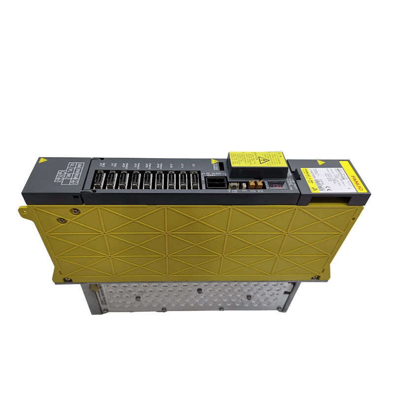
Fanuc A06B-6079-H201 | 2-Axis Alpha Servo Amplifier Module — SVM2-12/12, 3.0A × 2 Axes, 283–325V / 1.5kW, 230V Output, Sine-Wave PWM IGBT, Type A/B
Overview
The Fanuc A06B-6079-H201 is a two-axis alpha series servo amplifier module from the SVM2-12/12 class — a dual-channel drive module that controls L and M axis connections simultaneously, each rated at 3.0A continuous output from a 283–325V DC bus input.
The compact 60mm module width and dual-axis architecture make the H201 one of the most commonly encountered alpha series modules in the field: two axes in 60mm of cabinet rail space fits naturally into the machining centre configuration where two of the three primary axes are small α motors running at loads within the 12A peak / 3.0A continuous current envelope.
The SVM2-12/12 current class is sized for the smaller alpha servo motors — α1/3000, α2/2000, and α2/3000 — that drive the lighter-load axes of compact and mid-size CNC machine tools and wire EDM machines.
In a three-axis machining centre where the X and Y axes are driven by α1 or α2 motors and the Z axis requires a heavier motor, the typical drive configuration pairs an H201 (SVM2-12/12) for the X and Y axes with a larger single-axis SVM for the Z axis.
This mixed-module approach is common in Fanuc alpha series installations and allows the machine builder to optimise cabinet width and cost by using only the current capacity actually required for each axis.
The sine-wave PWM control method implemented in the H201's IGBT bridge produces smooth motor current waveforms that minimise torque ripple — the small periodic torque variation that arises from less-ideal current waveform shapes in trapezoidal or six-step PWM drives.
For CNC machining axes where surface finish quality is affected by axis velocity ripple, the sine-wave PWM approach is the standard that all alpha-series drives implement.
Key Specifications
| Parameter |
Value |
| Module Model |
SVM2-12/12 |
| Axes |
2 (L, M channels) |
| Rated Input |
283–325V DC, 1.5 kW |
| Max Output Voltage |
230V AC |
| Rated Output Current |
3.0A per axis (L and M) |
| Control Method |
Sine-wave PWM, IGBT bridge |
| Interface |
Type A or Type B |
| Wiring Board |
A16B-2202-077x |
| Control Card |
A20B-2001-09xx |
| IPM Modules |
Two 20A per axis |
| Module Width |
60 mm |
| Compatible Motors |
α1/3000, α2/2000, α2/3000 |
Dual-Axis Architecture — Two Independent Channels
The SVM2-12/12's two axis channels are electrically independent output stages sharing a common DC bus and control electronics housing.
Each channel has its own IPM (Intelligent Power Module) transistor assembly rated at 20A peak, its own current measurement circuit, its own fault detection, and its own 7-segment alarm display output.
When one channel develops a fault, the CNC's alarm display identifies the specific axis and fault code, allowing fault isolation to the L or M channel without pulling the module from service if the fault does not require emergency shutdown of the other axis.
The shared wiring board (A16B-2202-077x) routes signals between the CNC serial interface, the two control card sections, and the two output stages.
The control card (A20B-2001-09xx) manages the current control algorithms for both axes simultaneously in its DSP firmware.
Neither board is available separately from Fanuc — faults on these boards require module exchange, while component-level faults on the IPM modules, cooling system, fuses, and batteries can be addressed on the bench.
Sine-Wave PWM and IGBT Bridge — Smooth Motion Control
The sine-wave PWM (pulse-width modulation) control implemented in the A06B-6079-H201 generates motor phase current waveforms that closely approximate true sinusoids.
The IGBT (Insulated Gate Bipolar Transistor) bridge switches at high frequency, and the PWM duty cycle modulates continuously to produce the desired motor current magnitude and phase angle at each moment of the electrical cycle.
For the connected alpha servo motors, sinusoidal current produces the smoothest torque output across the motor's speed range — from near-zero speed during fine positioning to full rapid traverse speed.
This smooth torque characteristic is what enables the tight contouring accuracy that CNC machining centres achieve on complex curved surfaces, where axis velocity changes continuously and any torque ripple would produce visible tool marks on the workpiece.
Current limiting and voltage regulation functions within the H201's control algorithm protect both the module's output transistors and the connected motors from fault conditions. Overcurrent protection responds in microseconds through the IPM's built-in hardware protection, faster than the firmware control loop, providing the first line of defence against short-circuit conditions.
FAQ
Q1: What is the rated continuous output current of the SVM2-12/12 — is it 12A or 3.0A per axis?
The "12" in SVM2-12/12 refers to the peak output current class (approximately 12A peak per axis), which is the basis for the module model name in Fanuc's naming convention. The rated continuous output current is 3.0A per axis — the sustained current the drive can deliver under prolonged machining load without thermal overload.
Peak current is available for short acceleration transients. When selecting compatible motors, verify the motor's rated continuous current falls at or below 3.0A; verify the motor's peak current at acceleration does not exceed the 12A peak capability.
Q2: The H201 can use either Type A or Type B interface — how is the correct type determined?
The interface type is determined by the CNC control generation and the machine's servo configuration. Type A interface is associated with the A06B-6079 series in older system configurations; Type B is associated with the A06B-6080 series but can also appear in some A06B-6079 configurations.
In practice, the type is defined by the serial interface connector wiring on the CNC's axis card and the motor's pulse coder type. The safest approach is to confirm the interface type from the machine's existing drive before sourcing a replacement — an incorrect interface type produces communication alarms on the CNC and prevents servo operation.
Q3: What alpha servo motors are compatible with the A06B-6079-H201?
The SVM2-12/12's 3.0A/12A continuous/peak current ratings are matched to the smaller alpha series motors: the α1/3000 (rated 0.5kW, 3000rpm), the α2/2000 (rated 0.5kW, 2000rpm), and the α2/3000 (rated 0.5kW, 3000rpm).
These motors are the standard axis drives for compact machining centres, turning centres with small X/Z axes, and wire EDM machines.
The motor-to-module match must be exact — the CNC's servo parameter initialisation requires the motor model number to be entered, and the firmware uses this to set the correct current loop gains, current limits, and velocity feedback scaling for that specific motor.
Q4: Can both L and M axis channels be used simultaneously at full rated current?
Yes. The SVM2-12/12 is rated for simultaneous full-current operation on both L and M channels — the 1.5kW input power rating encompasses both axes operating at their rated continuous output.
The DC bus capacity supplied by the PSM must be sufficient for both axes simultaneously, which it is in a standard alpha series PSM-SVM cabinet configuration.
During rapid traverse movements where both axes accelerate simultaneously, the regenerative capability of the PSM handles the energy recovery from both motor deceleration phases.
Q5: Storage and handling — what environmental conditions should be observed for the A06B-6079-H201?
The H201 should be stored indoors in a dry, climate-controlled environment. The recommended storage temperature range is −20°C to +60°C (ambient); avoid direct sunlight during storage as sustained UV and heat exposure can degrade connector plastics and PCB surface coating.
Do not store in environments with condensation risk — the IGBT modules and PCB components are susceptible to moisture-induced corrosion on solder joints and copper traces. Before installing a stored module, visually inspect the internal components for signs of corrosion or physical damage, and verify that the backup battery voltage is adequate before powering the system.

 Your message must be between 20-3,000 characters!