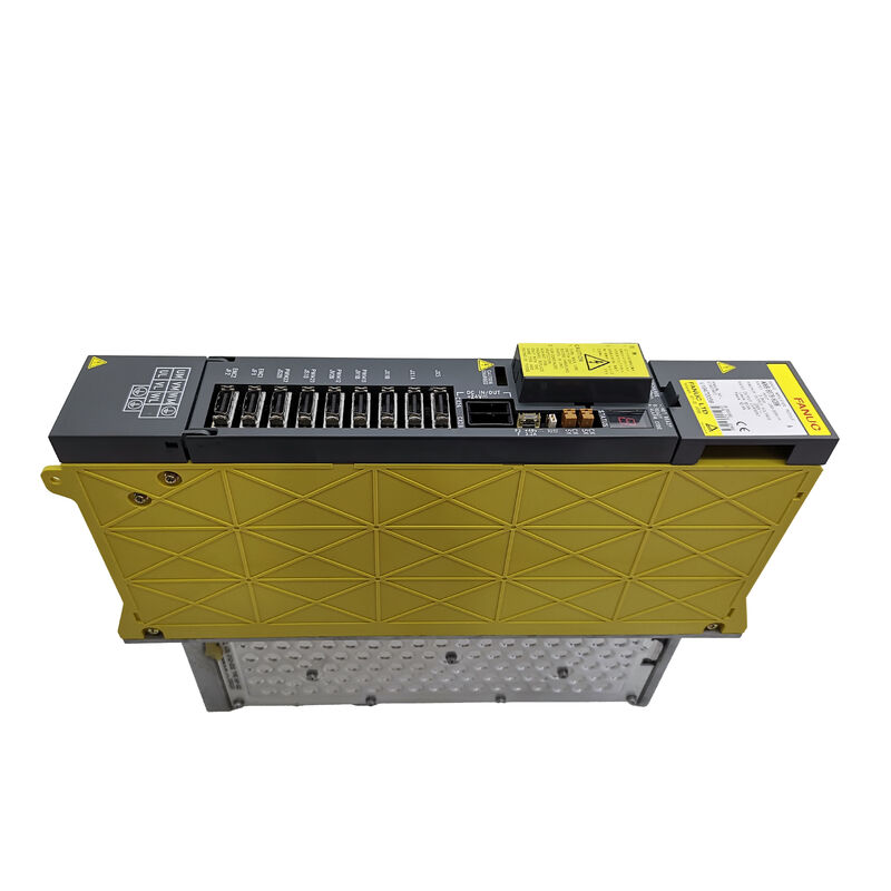
FANUC A06B-6079-H106 | Alpha SVM1-130 Single-Axis Servo Amplifier Module — 9.1 kW / 52.2A, Japan Origin
Part Number: A06B-6079-H106
Manufacturer: FANUC Corporation (Japan)
Product Type: Single-Axis Servo Amplifier Module (SVM1)
Model: SVM1-130
Series: Alpha Servo Amplifier (A06B-6079)
Rated Input: 283–325V DC / 9.1 kW
Maximum Output Voltage: 230V AC
Rated Output Current (L Axis): 52.2A
Interface: Type A / Type B (selectable via JS1B & JV1B jumpers)
Dimensions: H 380 × W 90 × D 307 mm
Weight: 11 lb (approx. 5 kg)
Overview
The A06B-6079-H106 is the SVM1-130 — the 130A class single-axis servo amplifier module in FANUC's Alpha series drive system. It is one of the higher-rated modules in the A06B-6079 SVM1 family, designed for the servo axes that drive large, heavy cutting tools or large workpiece carriers where substantial torque is required. With a 9.1 kW power input rating and 52.2A continuous output current, it serves the full range of FANUC's Alpha 22 through 40 motor class, making it the appropriate drive for the most demanding axis applications in the Alpha series motor range.
This module draws DC bus power from the Alpha system's PSM (Power Supply Module) and converts it to variable-frequency, variable-voltage AC output to drive the connected servo motor. The SVM1-130 handles one servo axis.
The motor type it is typically matched with — Alpha 22 through 40 class — represents large-frame, high-torque servo motors used in machining centres and turning centres where significant cutting forces are involved.
Type A and Type B interfaces are supported, selectable through the JS1B and JV1B jumpers on the unit's front face.
This makes the SVM1-130 compatible with a wide range of FANUC CNC controllers from the Series 16 through Series 21 generation. The interface type must match the CNC controller's servo interface setting for the drive to communicate correctly.
One configuration detail is important for correct ordering: the A06B-6079-H106 may be fitted with either one or two CX5 battery connector ports, depending on the hardware revision.
The CX5 port is used for the absolute encoder battery connection. Specifying the correct CX5 configuration when ordering is necessary to ensure the replacement unit matches the original installation.
Key Specifications
| Parameter |
Value |
| Part Number |
A06B-6079-H106 |
| Manufacturer |
FANUC Corporation |
| Model |
SVM1-130 |
| Type |
Single-Axis Servo Amplifier Module |
| Rated Input |
283–325V DC, 9.1 kW |
| Maximum Output Voltage |
230V AC |
| Rated Output Current (L Axis) |
52.2A |
| Interface |
Type A / Type B (jumper selectable) |
| Compatible Motors |
Alpha 22, 30, 40 series |
| Compatible CNC |
Series 16MA/MC/TB, 18MC/TA/TB, 21MB/TB |
| Dimensions |
H 380 × W 90 × D 307 mm |
| Weight |
11 lb (approx. 5 kg) |
| Control Board |
A20B-2100-0932 |
| Wiring Board |
A16B-2202-0790 |
| Operating Temperature |
0 – 55°C |
| Max. Altitude |
1,000 m |
| Condition Available |
New (surplus) / Refurbished / Repaired / Exchange |
SVM1-130 in the Alpha Drive System
The Alpha SVM series operates on FANUC's shared DC bus architecture. The PSM generates and maintains the DC bus voltage.
The SVM1-130 draws from this bus and drives the servo motor. This arrangement means the SVM1-130 does not need its own AC power input — it relies entirely on the DC bus that the PSM provides. The SVM1-130's internal DC bus connections are the primary power input to the unit.
The SVM1-130's high current rating — 52.2A — puts it at the upper end of the single-axis Alpha module range.
This current capacity reflects the needs of the motors it drives. An Alpha 22 motor operating at its rated torque requires sustained current delivery at the servo amplifier's full rated output.
An Alpha 40 motor at full torque requires even more. The SVM1-130's rating accommodates these loads with headroom for the dynamic current peaks that occur during rapid acceleration.
The internal structure of the SVM1-130 follows the standard Alpha SVM layout: a control board and a wiring board. The A20B-2100-0932 control board executes the servo control algorithms — position loop, velocity loop, and current loop — while the A16B-2202-0790 wiring board provides the power-stage gate drive and current sensing.
Both boards are individually replaceable when a targeted repair is preferred to complete unit replacement.
Alarm Reference
The A06B-6079-H106 displays single-character alarm codes on its front-mounted LED display. The most common alarms seen in field service include:
Alarm 1 indicates the internal cooling fan has stopped.
The fan is critical for maintaining the IGBT transistors within their thermal limits. A stopped fan will progress to an overtemperature condition within minutes of heavy operation.
Alarm 2 indicates low control power voltage. Alarm 5 indicates low DC link voltage — the bus voltage from the PSM is below the operating threshold.
Alarm 8 indicates L-axis overcurrent, the most common alarm indicating a motor phase fault, a motor cable short, or degraded IGBTs in the power stage. IPM alarms (codes with a dot) indicate an Intelligent Power Module fault — typically overtemperature or short circuit within the IGBT module itself.
Application Context
Machines documented to use the A06B-6079-H106 include the Youji YV1200 vertical machining centre and the Mori Seiki SL-250 turning centre, among many others. The CNC controllers these machines typically use span the FANUC 16MA, 16MC, 18TA, 18MC, 21TB, 16TB, 18TB, and 21MB platforms.
FAQ
Q1: The SVM1-130 shows Alarm 8 (L-axis overcurrent). The motor cables have been checked and appear undamaged. What should be investigated next?
After confirming motor cable integrity, test the motor's winding resistance and insulation to ground with an insulation tester.
A degraded motor winding can draw asymmetric phase current that registers as overcurrent at the drive.
If the motor tests good, the drive's IGBT power module may have degraded — a marginal IGBT can fail under load current even when it passes static testing.
A qualified drive repair service can test the IGBTs under dynamic load conditions.
Q2: A replacement A06B-6079-H106 has been sourced. What jumper settings need to be verified before installation?
The Type A / Type B interface selection is set by the JS1B and JV1B jumpers on the unit's front face.
The jumper configuration must match the original unit exactly, as it must correspond to the CNC controller's servo interface setting for that axis.
The number of CX5 battery ports on the replacement must also match the original unit's configuration.
Confirm both settings before installation to avoid communication errors or battery connection problems after power-on.
Q3: The drive initialises correctly but the axis produces audible noise and vibration at low speeds. No alarm is generated. What is causing this?
Low-speed noise and vibration with no alarm suggest a current loop disturbance — either a small asymmetry in the IGBT switching that creates current ripple, or a degraded component in the current measurement circuit that introduces noise into the current feedback.
Check the servo parameters for any changes from the previous correct values. If parameters are confirmed unchanged, the drive's current measurement circuit is likely degraded.
Q4: This drive is discontinued by FANUC. How can a reliable replacement be found?
Tested surplus units from decommissioned machines, professionally refurbished units with replaced aging components and functional testing under motor load, and 24-hour repair services are all available from the aftermarket supply chain.
The critical requirement is that any replacement — whether surplus or refurbished — has been functionally tested under actual motor load in a closed-loop servo system, not just powered on without a motor connected.
Static testing does not confirm the drive's ability to regulate current under dynamic motor loading.
Q5: After replacing the SVM1-130, the axis positioning accuracy has slightly degraded compared to the previous unit. All parameters have been restored from backup. What should be checked?
Slight accuracy degradation after drive replacement with correct parameters is often related to the encoder feedback cable — specifically, the cable's signal integrity or the connector contacts.
The replacement drive's encoder input circuit may be slightly different in its signal threshold, exposing marginally connected cable joints that the original drive tolerated. Inspect and reseat the encoder feedback connectors.
Also verify the replacement drive's hardware revision matches the original — different hardware revisions can have slightly different gain characteristics.

 Your message must be between 20-3,000 characters!