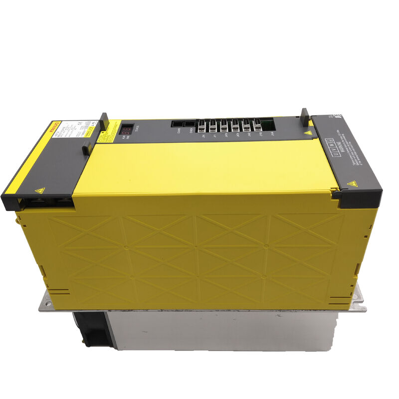
FANUC A06B-6141-H022 — αiSP 22 Type A Spindle Amplifier Module | 200V, 95A, 25.2kW
Part No.: A06B-6141-H022 (#H580) ▏Series: αi SP Type A ▏Model: αiSP 22 / AiSP-22 ▏Voltage Class: 200V Input ▏Condition: New Original
What This Unit Is and Who Needs It
When a spindle alarm shuts down a machining centre running a FANUC 16i, 18i, or 21i control, the A06B-6141-H022 is one of the most frequently required replacement parts in that control generation. It is the Type A interface variant of FANUC's αiSP 22 spindle amplifier — a module that controls a single αi-series spindle motor in the 22kW continuous power class, drawing from the cabinet's shared αiPS DC bus and delivering regulated three-phase AC to the spindle motor.
The "Type A" designation is not a quality grade — it refers specifically to the physical connector and communication interface format between the amplifier and the CNC. Type A was the original interface used in the first release of the αi series, and it remains the correct specification for a large installed base of 16i/18i-generation machine tools still in production worldwide. Its successor for the same CNC generation — the Type B / B2 variant (A06B-6142-H022) — uses an updated connector layout and may require a CNC parameter adjustment when substituted. For machines that shipped with a Type A unit, sourcing A06B-6141-H022 directly is the safest path to a like-for-like restoration.
Technical Specifications
| Parameter |
Value |
| Part Number |
A06B-6141-H022 (#H580) |
| Series |
αi SP — First-Generation Alpha i Spindle |
| Interface Type |
Type A |
| Voltage Class |
200V Input (#H580) |
| DC Bus Input Voltage |
283 – 339 V DC |
| Spindle Power Rating |
25.2 kW |
| Rated Output Voltage |
240 V AC, 3-phase |
| Rated Output Current |
95 A |
| Architecture |
Shared DC bus (αiPS PSM required) |
| Enclosure |
IP20 |
| Compatible CNC Platforms |
FANUC Series 16i / 18i / 21i / Power Mate i |
The αiSP 22 Family — Type A, Type B, and the Newer αiSP-B: What's the Difference?
Three separate part numbers describe a 22kW FANUC αi spindle amplifier, and mixing them up is the most costly sourcing mistake in this category. The table below clarifies the distinctions:
| Part Number |
Interface |
Target CNC |
Key Difference |
| A06B-6141-H022 |
Type A |
16i / 18i / 21i |
Original connector; this product |
| A06B-6142-H022 |
Type B / B2 |
16i / 18i / 21i |
Updated connector layout, same power class |
| A06B-6220-H022 |
FSSB (αiSP-B) |
0i-D / 30i / 31i |
Newer fibre-optic bus generation — NOT compatible with 16i/18i |
The A06B-6141-H022 and A06B-6142-H022 can sometimes substitute for each other within the same CNC generation, but only after confirming that the CNC firmware revision supports the connector variant and that the spindle amplifier type parameter is updated. The A06B-6220-H022 is a completely different electrical architecture and should never be ordered as a replacement for a 16i/18i machine without a full CNC upgrade.
Compatible Spindle Motors
The αiSP 22 Type A is calibrated for FANUC's α-series spindle motors in the 22kW power band. Its 95A rated output accommodates the following motor families:
αiI — Integrated spindle motors
- αiI 22/6000 — 22kW, 6,000 rpm; the primary matched motor for this amplifier
- αiI 18/8000 — 18kW at 8,000 rpm; within the amplifier's output headroom
αiIP — In-spindle integral type
- αiIP 22/8000 — through-spindle direct-drive motor for high-speed machining centres
αiIL — In-line (external) type
- αiIL 22/6000 — motor driving the spindle via gearbox or belt reduction
All motor selections should be cross-referenced against the motor's continuous current draw at rated load to ensure it stays within the 95A output limit. The kW rating is a nominal power class, not a guaranteed compatibility ceiling — always verify from the motor specification sheet.
Shared DC Bus Architecture: Implications for the Whole Cabinet
The A06B-6141-H022 does not rectify its own mains supply. It receives regulated DC power from the αiPS power supply module, which acts as the central rectifier and energy manager for the entire amplifier stack in the cabinet. This shared architecture has two practical consequences worth understanding:
Regenerative energy sharing. When the spindle decelerates rapidly, it generates back-EMF that feeds energy back onto the DC bus. Rather than burning this energy in a resistor, the αiPS redistributes it to other modules that are simultaneously drawing power — servo axes accelerating, for example. This reduces overall cabinet heat load and lowers electricity consumption during high-cycle production.
PSM sizing is critical. If the αiPS is replaced or if additional axes are added to the cabinet, the PSM's continuous output rating must cover the combined peak demand of the spindle module plus all servo axis modules simultaneously. An underpowered PSM produces DC bus undervoltage alarms during peak demand moments — a symptom that is sometimes incorrectly diagnosed as a failing spindle module.
Spindle Functions: Orientation, Rigid Tapping, Cs Contouring
Beyond basic speed control, the αiSP 22 Type A supports the full set of FANUC spindle functions:
Spindle orientation brings the spindle to a precise angular stop — essential for automatic tool changers, pallet indexing, and any operation where the spindle must park in a defined rotational position. The accuracy of the stopped position depends on the position coder resolution installed on the spindle motor.
Rigid tapping synchronises spindle rotation with Z-axis feed to cut threads without a floating tap holder, improving thread accuracy and enabling tapping at higher speeds. This function requires the CNC rigid tapping software option and a spindle motor fitted with an appropriate encoder.
Cs contouring places the spindle under full closed-loop position control, allowing it to be programmed as a rotary C-axis for milling operations on a turning centre. This requires a high-resolution spindle encoder and the corresponding CNC software option.
All three are hardware-supported by this amplifier. Their availability on a given machine depends entirely on the CNC software options that were purchased at the time of original commissioning.
Common Alarm Codes Reference
| Alarm |
Most Likely Cause |
| AL-01 |
Spindle motor overheat — check cooling, ambient temperature, duty cycle |
| AL-07 |
DC bus overvoltage — deceleration too fast for PSM regeneration capacity |
| AL-09 |
DC bus undervoltage — check PSM mains input and DC bus connections |
| AL-12 |
Spindle motor overcurrent during acceleration |
| AL-24 |
Output transistor (IGBT) fault — power stage issue |
| AL-30 / AL-31 |
Cooling fan speed reduction or failure |
For AL-07 specifically: before replacing the amplifier, try increasing the spindle deceleration time constant in the CNC parameters. Rapid spindle stops on large-inertia spindles frequently produce bus overvoltage alarms that are entirely parameter-correctable without hardware intervention.
Part Number Cross-Reference
| Format |
Notation |
| Standard |
A06B-6141-H022 |
| With voltage suffix |
A06B-6141-H022#H580 |
| Hyphen-free |
A06B6141H022 |
| OCR misread variant |
AO6B-6I4I-HO22 |
| Common label shorthand |
αiSP 22 / AiSP-22 / AISP-22 / Alpha iSP22 |
| Type B equivalent (same power) |
A06B-6142-H022 — interface varies |
| FSSB-generation successor |
A06B-6220-H022 — different CNC generation |
Shipping & Logistics
Dispatch: Stock units ship within 1–2 business days of order confirmation. Each module includes the complete power board and control PCB, packed in anti-static wrap inside foam-padded rigid carton.
Carriers: DHL Express · FedEx International Priority · UPS Worldwide Express · TNT · EMS — carrier matched to destination and urgency.
Transit: Express services deliver to 220+ countries within 24–48 hours. Standard international transit 3–7 business days.
Customs: Commercial invoice and packing list provided with every shipment. Import duties and taxes are the buyer's responsibility under the importing country's regulations.
FAQ
Q1: My machine has a Type B spindle amplifier (A06B-6142-H022) that has failed. Can I fit a Type A (A06B-6141-H022) as a substitute? In the same CNC generation (16i/18i/21i), Type A and Type B αiSP 22 amplifiers drive the same motors with the same power ratings. Whether a Type A can substitute for a Type B depends on whether your CNC firmware revision supports the Type A connector variant and whether the spindle amplifier type parameter in the CNC can be reconfigured to accept it. On later 16i/18i revisions that shipped with Type B as standard, a Type A substitution may work but requires parameter adjustment — it should not be attempted as a blind swap. Contact a FANUC integrator or check the CNC firmware documentation before proceeding.
Q2: What αiPS power supply module should be paired with the A06B-6141-H022 in a standard three-axis machining centre cabinet? The αiPS must be rated to supply the combined peak current demand of the spindle module plus all servo axes simultaneously. For a typical three-axis VMC with this spindle module alongside 20A-class servo axes, the αiPS 30 or αiPS 45 are common selections — but the exact choice depends on the servo motor configuration. FANUC provides a load calculation method in the amplifier description manual (B-65282) that accounts for motor continuous current, duty cycle, and simultaneous axis operation. Always complete this calculation rather than estimating, particularly when replacing a PSM alongside this spindle module.
Q3: After fitting a replacement A06B-6141-H022, the CNC shows SP9001 (spindle not ready). What are the most likely causes? SP9001 indicates the spindle amplifier is not asserting its ready signal to the CNC. After a module swap, this most commonly occurs because: (1) the spindle amplifier type parameter in the CNC still references the old unit — run the spindle initialisation procedure from the CNC's servo/spindle setting screen; (2) the 24V DC control power to the new module is not properly established — check the CX2A control power connector; (3) there is a loose or improperly seated connector between the CNC and the spindle amplifier interface — check all JY and JX connector positions. If the alarm persists after verifying all three, check the DC bus voltage to confirm the αiPS is providing regulated DC to the new module.
Q4: The machine spindle previously ran at 8,000 rpm maximum. After the amplifier replacement, top speed is limited to 4,500 rpm. What has changed? Maximum spindle speed is typically limited by one of three parameters: the spindle motor's rated maximum speed, the amplifier's output frequency ceiling, or the CNC spindle speed limit parameter (usually parameter No. 3741 or equivalent depending on the control series). After a module replacement, if the spindle initialisation was performed, the CNC may have re-populated some spindle parameters from default values that differ from the machine-specific settings. Compare the current spindle parameter set against the machine's original parameter backup — the maximum speed clamp parameter in the CNC is the most likely candidate for having been reset to a lower default value.
Q5: Is it safe to run this amplifier with the cabinet door open during initial commissioning and testing? The DC bus inside the αi amplifier stack operates at approximately 283–339V DC under normal conditions — a lethal voltage. Additionally, the bus capacitors retain this charge for several minutes after the αiPS main power is removed; a charge LED on the PSM indicates when the bus has discharged to a safe level. Running with the door open during commissioning is sometimes necessary for monitoring indicator LEDs, but all work near the DC bus terminals, connector insertion, and cable adjustment must be performed with the main power fully disconnected and the charge LED confirmed off. Partial-power testing (control power only, main circuit isolated) is the safest approach when checking communication and parameter initialisation before committing to full-power motor runs.

 Your message must be between 20-3,000 characters!