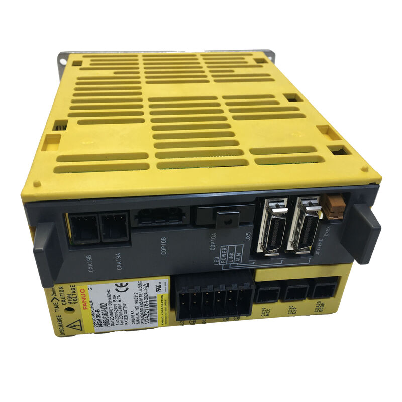
FANUC A06B-6160-H002 Servo Amplifier — βiSV20-B Single-Axis Unit, 200V, FSSB
Part No.: A06B-6160-H002 ▏Model: βiSV20-B ▏Type: Single-Axis AC Servo Amplifier ▏Voltage Class: 200V Input ▏Interface: FSSB Fibre-Optic ▏Condition: New Original
Overview
Pick up any compact FANUC-controlled turning centre or vertical machining centre running a 0i-D generation control, and there is a good chance the X or Y axis is driven by a unit exactly like this one. The A06B-6160-H002 — model designation βiSV20-B — is the workhorse single-axis servo amplifier of FANUC's Beta i series, sized for light-to-medium duty feed axes paired with βiS 2 through βiS 8 series servo motors.
It belongs to the A06B-6160 standalone amplifier family: a line of single-axis drives that connect directly to three-phase or single-phase 200–240V AC mains without requiring a separate power supply module. Each unit is fully self-contained, handling its own rectification, DC bus management, and braking energy dissipation through a built-in regenerative resistor. CNC communication runs over FSSB (Fanuc Serial Servo Bus), FANUC's fibre-optic serial link, which gives the drive the same noise-immune servo bus interface found across the full αi and βi amplifier range.
At 20A peak output, the H002 is correctly sized for the light-duty axis category. Using a higher-rated unit in its place is generally harmless if parameters are reconfigured; using a lower-rated unit (the H001) is undersizing; substituting the externally similar A06B-6160-H003 (βiSV40-B) without reconfiguring the CNC servo parameters creates a mismatch between the amplifier's capabilities and the CNC's current limit settings, leading to axis faults.
Electrical Specifications
| Parameter |
Value |
| Part Number |
A06B-6160-H002 |
| Model Code |
βiSV20-B |
| Axes |
1 (single axis) |
| Peak Output Current |
20 A |
| Rated Continuous Current |
6.5 A |
| Output Voltage |
240 V AC |
| Main Input Voltage |
200–240 V AC, 3-phase or 1-phase (+10% / −15%), 50/60 Hz |
| Control Supply |
DC 24 V |
| PWM Method |
Sine-wave, HRV2 / HRV3 |
| Regeneration |
Built-in resistor (no external unit required) |
| Communication |
FSSB fibre-optic (Fanuc Serial Servo Bus) |
| Feedback |
Serial pulse coder / absolute encoder (βiS-compatible) |
| Enclosure |
IP20 |
| Compatible CNC |
0i-D / 0i-MD / 0i-TD / 0i-Mate-D / 0i-MF |
Selecting the Right Model: A06B-6160 Series at a Glance
All four models in the 6160 single-axis range share the same physical format and FSSB interface. Choosing correctly means matching the motor's continuous current draw to the amplifier's rated output — not its peak:
| Part Number |
Model |
Peak |
Continuous |
Typical Motor |
| A06B-6160-H001 |
βiSV4-B |
10 A |
2.5 A |
βiS 0.5 / βiS 1 |
| A06B-6160-H002 |
βiSV20-B |
20 A |
6.5 A |
βiS 2 / βiS 4 / βiS 8 |
| A06B-6160-H003 |
βiSV40-B |
40 A |
13 A |
βiS 8 / βiS 12 / βiS 22 |
| A06B-6160-H004 |
βiSV80-B |
80 A |
25 A |
βiS 30 / βiS 40 |
The H002 and H003 are visually nearly identical. The front-panel label is the only field-reliable identifier — always verify it before ordering a replacement.
Compatible Servo Motors
The βiSV20-B's 6.5A continuous / 20A peak output is a good match for the following βiS motor frame sizes:
- βiS 2/4000 — low-inertia compact motor; current draw well within ratings at any duty cycle
- βiS 4/4000 and βiS 4/5000 — standard light-axis motors found on most 0i-D turning and milling machines; the most common pairing for this amplifier
- βiS 8/3000 — medium-frame motor; confirm the axis duty cycle keeps continuous current demand below 6.5A in sustained cutting passes
For βiS 8/2000 and larger frames, the continuous current demand under heavy cutting may approach or exceed the H002's rated output — at that point the βiSV40-B (A06B-6160-H003) is the appropriate selection.
Two Inputs, One Common Mistake
The A06B-6160-H002 has two electrically separate power connections that are both required for normal operation:
CX29 — Main Circuit (200–240V AC) Drives the motor. Accepts three-phase or single-phase input. Wire gauge should be rated for 20A with adequate margin, particularly if the supply run is long. Voltage sag on this line during axis acceleration is a frequent source of intermittent servo alarms that can be difficult to trace without a power quality analyser.
CX2A — Control Circuit (DC 24V) Powers the logic board, FSSB interface, and encoder circuits. This supply must remain live whenever the CNC is in a ready state, even during maintenance when the main 200V breaker is opened. Dropping the 24V while the FSSB is active causes a communication disconnection alarm that clears only after a full power cycle. Cross-wiring these two inputs is a damaging error that is more common than it should be during first-time installation.
Direct Mains Architecture — No PSM Needed
Engineers transitioning from αi-B series installations sometimes look for a companion power supply module (PSM) before commissioning a βiSV-B drive. There isn't one — and none is needed. Unlike the αiSV-B, which draws from a shared DC bus fed by an αiPS-B PSM, the βiSV-B series has its own internal rectifier and DC bus capacitor. Each unit is independently mains-powered. This simplifies cabinet wiring for auxiliary axis additions and means the βiSV40-B or βiSV20-B can be mounted wherever a mains feed is accessible, without calculating shared bus headroom.
The consequence of this architecture is that braking energy is handled within the unit through the internal resistor rather than returned to a shared bus. For standard CNC axis duty cycles this is entirely adequate. Applications with unusually frequent rapid reversals may require an external regenerative resistor to supplement the internal unit's thermal capacity.
Part Number Cross-Reference
| Format |
Notation |
| Standard |
A06B-6160-H002 |
| No-hyphen |
A06B6160H002 |
| OCR variant (O / i substitution) |
AO6B-6I6O-HOO2 |
| Model designation |
βiSV20-B / Beta iSV20-B / BiSV20 |
| Next model up (higher current) |
A06B-6160-H003 — not interchangeable without parameter update |
Shipping & Logistics
Dispatch: Orders on stocked units are processed and shipped within 1–2 business days. Units are packed with anti-static protection inside foam-lined rigid cartons; where additional protection is warranted for transit, reinforced crating is used.
Carriers: DHL Express · FedEx International Priority · UPS Worldwide Express · TNT · EMS
Delivery: Express services cover 220+ countries with 24–48 hour transit times. Standard international delivery is 3–7 business days to most destinations.
Import duties: Assessed and payable by the buyer under the importing country's customs regulations. Commercial invoice and packing list provided with all shipments.
FAQ
Q1: My machine has a failed A06B-6160-H003 but I can only source the H002 quickly — can I fit the H002 temporarily? This substitution carries real risk and is not recommended even as a short-term measure. The H003 (βiSV40-B) is typically paired with motors that demand up to 13A continuous — double the H002's rated output of 6.5A. Running the H002 at sustained overcurrent will trigger thermal protection and may damage the output IGBT stage within a short time. If the motor on that axis is a βiS 8 or smaller and the duty cycle is light, the risk is lower, but it should not be assumed safe without checking the motor specification first. The correct approach is to source the H003 directly or use an H004 (βiSV80-B) as the higher-rated substitute, updating the CNC servo parameters accordingly.
Q2: After installing a new H002, the CNC shows "servo amplifier not ready" and the FSSB configuration screen shows an unrecognised module. What needs to be done? The FSSB auto-configuration must be run from the CNC's servo setting screen before the new amplifier will be recognised. Power the machine up, navigate to the FSSB setting screen (typically under System → Servo → FSSB), and execute the amplifier auto-detection. The CNC will scan the fibre-optic bus, identify the new βiSV20-B, and populate the amplifier type parameter for that axis. If the screen still shows an unrecognised module after auto-detection, check the fibre-optic cable seating at both the CNC optical port and the JOP/JOP2 connector on the amplifier — a partially seated plastic optical connector is the most common cause of FSSB detection failure.
Q3: Can the built-in regenerative resistor handle the braking demands of a tool changer or ATC arm axis? Most ATC arm movements are short, fast, and relatively infrequent — a tool change every 10–30 seconds at most on busy machines. The internal resistor has sufficient thermal capacity for this duty cycle in the vast majority of installations. Where the resistor becomes limiting is on high-cycle applications: pallet shuttles that index every few seconds, or oscillating axes in automated assembly equipment. In those cases, monitor whether a regeneration overheat alarm appears during sustained production. If it does, reducing the axis acceleration rate reduces peak braking power, and if that is not acceptable, an external regenerative resistor should be added.
Q4: Does this amplifier support the high-resolution absolute encoder used on newer βiS motors? Yes. The βiSV20-B supports FANUC's serial absolute pulse coder (the αA and βA encoder types), which allows the machine to retain axis position through power cycles without requiring a reference return. The CNC parameter set must specify absolute encoder type for the axis, and the encoder battery backup — either in the CNC cabinet or in the amplifier itself depending on the configuration — must be maintained. If the battery voltage drops below threshold, the absolute position data is lost and a reference return will be required on the next power-up, even if the physical encoder itself is undamaged.
Q5: What is the expected service life of the internal components, and what should be proactively replaced during a scheduled maintenance window? The electrolytic capacitors on the DC bus are the primary life-limited component — they typically begin to degrade after 7–10 years of service in normal industrial environments, with heat and ripple current being the main aging factors. A capacitor in early degradation will cause the DC bus voltage to ripple more than the IGBT gate drivers expect, leading to intermittent overcurrent or undervoltage alarms that are difficult to reproduce reliably. The cooling fan (if fitted) is the second priority for proactive replacement. If the unit is opened during a planned shutdown, visually inspect the DC bus capacitors for any bulging of the top seal or discolouration of the PCB beneath them — either indicates imminent failure and the capacitors should be replaced before the unit is returned to service.

 Your message must be between 20-3,000 characters!