FANUC A860-2005-T301 Pulsecoder — αiI1000 Servo Motor Encoder for FANUC Alpha i CNC Systems
Brand: FANUC
Designation: Alpha i Incremental 1000 (αiI1000)
Part Numbers: A860-2005-T301 / A8602005T301 10-Pin Connector
Made in Japan | In Stock
The Component That Closes the Loop
Every closed-loop servo system depends on one thing working correctly: accurate, continuous feedback from the motor shaft to the controller. The motor provides the force. The amplifier manages the current. But without a functioning encoder reporting real position data at every moment, neither of those elements can do their job. Position commands go unverified. Speed profiles go unconfirmed. The axis operates open-loop — or not at all.
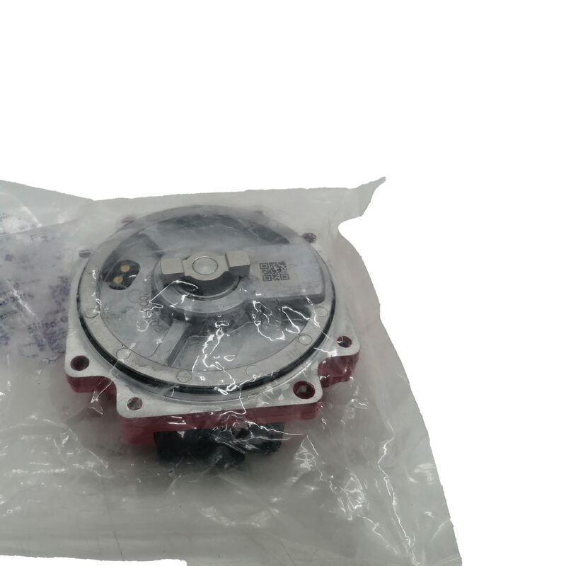
The FANUC A860-2005-T301 is the αiI1000-type pulsecoder installed in FANUC Alpha i series AC servo motors, spanning a wide range of machine tool and industrial automation applications. It is mounted inside the motor's rear endbell, coupled mechanically to the rotor shaft, and transmits one million feedback pulses per revolution to the servo amplifier through a 10-pin connector interface. Everything the CNC controller knows about where the axis is and how fast it is moving flows through this component.
When the pulsecoder fails — and the alarm codes that signal its failure are among the most disruptive events in a FANUC-controlled production environment — restoring the machine to operation means replacing this part with the correct unit, installed correctly, matched precisely to the motor label.
Part Identity at a Glance
| Parameter |
Detail |
| FANUC Part Number |
A860-2005-T301 |
| Common Designation |
αiI1000 (Alpha i Incremental 1000) |
| Encoder Type |
Incremental optical pulsecoder |
| Resolution |
1,000,000 pulses per revolution |
| Connector |
10-pin |
| Mounting |
Built-in, motor rear endbell |
| Motor Coupling |
Oldham's coupling |
| Compatible Motor Range |
FANUC Alpha i series αi4 through αi100 |
| Motor Voltage Classes |
200V AC and 400V AC (high voltage) |
| Speed Range |
3,000 r/min to 6,000 r/min rated motor variants |
| Origin |
Japan |
| Application |
CNC machine tools, servo-controlled automation |
Data sourced from FANUC AC Servo Motor αi Series Descriptions, Manual B-65262EN.
One Million Pulses Per Revolution — What That Means in a Real CNC Environment
The αiI1000 designation tells you that this encoder generates exactly one million discrete feedback signals for every complete motor shaft rotation. To put that in practical context: if a servo axis drives a ball screw with a 10mm pitch, one motor revolution moves the axis 10mm. One million encoder counts over that 10mm travel gives the controller a position resolution of 0.00001mm — 10 nanometers per count at the motor shaft before any mechanical reduction is considered. In reality, the achievable positioning accuracy of the machine depends on many factors beyond encoder resolution alone, but the encoder itself is not the limiting element.
What the 1,000,000 ppr resolution directly affects in day-to-day machining is the quality of velocity feedback at low speeds and during precise contouring moves. At very low feed rates — the kind used for finish passes, thread cutting, and synchronized tapping — coarse encoder resolution produces velocity ripple that shows up as surface irregularity on the finished part. Fine resolution eliminates that ripple at the source, giving the velocity control loop clean, continuous data to work with even when the axis is moving slowly.
This is why FANUC standardized this resolution across a broad range of Alpha i motor sizes rather than reserving it for high-end variants. Consistent feedback quality across the motor range simplifies CNC parameter management and ensures that performance characteristics are predictable regardless of which axis a given motor size is driving.
Incremental Type — The Operating Difference That Matters
Within the FANUC A860-2005 series, two types of pulsecoder are produced: incremental (this unit, αiI) and absolute (αiA, part number A860-2000-T301). Both achieve the same 1,000,000 ppr resolution. The operating difference is fundamental.
An absolute pulsecoder continuously stores and communicates a full, multi-turn position address. The servo amplifier battery maintains this position data through power-off periods. When the machine powers on, the controller immediately knows the absolute position of every axis — no movement required, no home position needed.
An incremental pulsecoder counts position changes from a reference established at power-on. It has no memory of absolute position between power cycles. When the machine starts up, each axis equipped with an incremental encoder must perform a reference return (home return) to establish a known starting position before the CNC can execute programs. This is a normal, designed-in operating procedure — not a limitation or a fault condition. It is simply how incremental systems work.
FANUC machines are configured at commissioning for either absolute or incremental feedback on each axis, and the servo amplifier parameters reflect that choice. The A860-2005-T301 is the incremental type. If the motor label shows this part number, the system is running incremental feedback on that axis. The replacement encoder must be the same type — swapping in an absolute pulsecoder on an incremental-configured axis will produce errors that prevent operation.
How to Confirm This Is the Correct Part Before Ordering
The single most important step before purchasing a replacement pulsecoder is reading the part number on the label attached to the encoder currently in the motor — not the motor's nameplate, but the encoder's own label on the rear endbell assembly.
The label will show one of the A860-series part numbers. If it reads A860-2005-T301, this listing is the direct replacement. If it reads A860-2000-T301 (absolute type), A860-2001-T301 (16 million ppr absolute), or any other variant, a different part is required. The full part number — including the prefix, base number, and suffix — must match exactly. Partial matches within the series are not interchangeable.
This verification step takes under a minute and eliminates the possibility of receiving the correct brand and general type but the wrong specification for the specific motor and amplifier combination.
Encoder Alarms — Typical Indicators of Pulsecoder Failure
FANUC CNC controllers report encoder-related faults through the servo alarm system. The alarm numbering varies by controller model (0i, 16i/18i/21i, 30i/31i/32i), but common alarm categories associated with pulsecoder failure include:
SV (Servo) alarms in the 300-series range on FANUC 0i and related controllers, specifically those indicating feedback signal abnormality, communication error between amplifier and encoder, or count error in the feedback path. On 30i/31i/32i systems, the corresponding alarms appear in different numbering ranges but describe the same underlying conditions.
These alarms can also result from a damaged encoder cable (the cable between CN2 on the amplifier and the motor encoder connector) or a failed servo amplifier CN2 interface circuit. Before condemning the pulsecoder, verify the cable — inspect for physical damage, bent pins, loose seating at either connector end. A cable swap with a known-good unit is the fastest way to isolate the fault to either the cable or the encoder. If the alarm follows the motor regardless of which cable is used, the pulsecoder itself is the likely failed component.
FANUC Alpha i Pulsecoder Series — Context for This Part
The A860-2005-T301 sits within a family of pulsecoders that share the same physical mounting format but differ in feedback type and resolution. Understanding the series prevents ordering errors:
| Part Number |
Type |
Designation |
Resolution |
| A860-2000-T301 |
Absolute |
αiA1000 |
1,000,000 ppr |
| A860-2005-T301 |
Incremental |
αiI1000 |
1,000,000 ppr |
| A860-2001-T301 |
Absolute |
αiA16000 |
16,000,000 ppr |
| A860-2010-T301 |
Absolute |
αi-AB128 |
128 positions/rev |
The A860-2000-T301 and A860-2005-T301 look similar externally and have the same resolution — they are not interchangeable. The A860-2001-T301 is a completely separate product with 16× higher resolution. The A860-2010-T301 is used in different application contexts entirely.
Installation Overview — Key Procedural Points
The A860-2005-T301 is replaced using the same procedure documented across the FANUC Alpha i motor range:
Four M4 hexagonal socket head bolts secure the pulsecoder at the motor endbell. These four bolts are removed; the M3 bolts positioned adjacent to each M4 bolt are motor assembly fasteners that must not be touched during this procedure. Loosening the M3 bolts compromises the motor's internal assembly and creates additional damage.
The pulsecoder is removed with its Oldham's coupling. A new coupling should be installed together with the new encoder — the coupling is inexpensive, and installing a worn coupling under a new encoder transfers existing misalignment-induced stress to the replacement unit from the first moment of operation.
The new pulsecoder is inserted until the O-ring seats fully in the groove between the motor pocket and the encoder body. The O-ring must not be pinched or caught out of its seat — a displaced O-ring leaves the motor endbell unsealed. The four M4 bolts are reinstalled and torqued.
Both the pulsecoder and the Oldham's coupling are precision components sensitive to physical shock and contamination. Keep them in their packaging until the moment of installation, and handle them without impact or exposure to cutting chips or coolant.
Counterfeit Awareness
FANUC parts — particularly high-demand encoder and amplifier components — are actively counterfeited. Non-genuine pulsecoders typically generate persistent alarm codes that cannot be cleared, or function intermittently before failing within a short service period. Counterfeit units are distributed through unverified channels and frequently labeled with accurate-looking FANUC markings and part numbers.
The practical protection is sourcing from suppliers who carry verifiable, documented stock. Genuine FANUC manufacture is confirmed by Japan-origin markings and consistent FANUC serial number and date code formatting on the encoder label. If there is any doubt about authenticity after receiving a unit, compare the label details and housing construction against known-genuine examples before installation.
FAQ
Q1: My machine is showing a FANUC SV alarm on one axis but the motor runs fine on another test. How do I know if the pulsecoder is bad or if it's the encoder cable?
This is a common diagnostic situation, and the cable is the right place to start because it is faster to swap and less expensive to replace than the pulsecoder. If you have two axes using the same cable type, temporarily connect the suspect axis motor to the working axis's encoder cable (while keeping the power wiring on the correct axis). If the alarm clears or follows the cable to the other axis, the cable is the fault. If the alarm stays with the motor regardless of which cable is plugged in, the pulsecoder is the likely failure. A second confirmation method is to connect the suspect motor to a known-good amplifier on a test rig or spare axis — if the same alarm appears immediately with a different amplifier and cable, the encoder is the cause. Do not assume the pulsecoder is bad until the cable has been eliminated.
Q2: After replacing the A860-2005-T301, the machine is demanding a reference return every time it powers on. Is this normal, or did something go wrong during installation?
This is entirely normal behavior for an incremental encoder system and has nothing to do with the installation quality. The αiI1000 type pulsecoder does not retain absolute position between power cycles — that is a fundamental characteristic of the incremental design. Every time the machine powers on, the servo system has no stored knowledge of where the axis is. The reference return establishes that knowledge by moving the axis to a known mechanical reference position, after which the controller tracks position incrementally from that starting point for the rest of the session. This is the standard operating procedure for all FANUC machines using incremental feedback. If a machine that previously used an absolute pulsecoder (αiA type) is now demanding a reference return after receiving an incremental replacement, that would indicate the wrong encoder type was installed — but if the A860-2005-T301 was always the encoder on this axis, the reference return requirement existed before the replacement as well.
Q3: Is the A860-2005-T301 compatible with FANUC robot controllers such as the R-30iB or R-30iA, or is it exclusively for CNC machine tool servo motors?
The A860-2005-T301 is primarily associated with FANUC Alpha i series AC servo motors used in CNC machine tool applications, where it is fitted to the motor during manufacturing. FANUC robot systems use their own servo motor and encoder families, which differ from the machine tool Alpha i series in both mechanical form and encoder protocol. While there may be specific robot servo motor configurations that use identical or similar pulsecoder hardware, replacement of robot encoder components should be confirmed against the specific robot motor's label part number and the robot controller's documentation rather than assumed from the CNC application compatibility. For CNC machine tool maintenance — VMCs, HMCs, turning centers, and similar equipment using Alpha i series servo motors — the A860-2005-T301 is the confirmed applicable part where the motor label matches.
Q4: What is the Oldham's coupling, and is it always necessary to replace it during a pulsecoder change?
The Oldham's coupling is a three-piece flexible coupling that sits between the motor shaft and the pulsecoder input. The center piece has drive slots on both faces that engage corresponding drive features on the motor shaft hub and the pulsecoder input disc. This arrangement transmits rotation from the motor shaft to the encoder while tolerating small amounts of axial and angular misalignment that are always present to some degree in real motor assemblies. Without the Oldham's coupling, any misalignment would apply bending and radial forces to the pulsecoder's internal bearing and optical assembly continuously during operation, leading to premature encoder failure. FANUC's own service documentation recommends installing a new coupling together with a new pulsecoder. The coupling has a finite service life and develops wear on its drive slots after extended operation. Reusing an old coupling under a new encoder means the new encoder inherits the old coupling's wear-induced misalignment from the first hour of service. The coupling is a low-cost item relative to the encoder — replacing it simultaneously is the correct procedure.
Q5: Can I source just the pulsecoder and install it on a motor myself, or does replacement typically require a FANUC service technician?
The pulsecoder replacement procedure is documented in FANUC's servo motor instruction manuals and is routinely performed by in-house maintenance engineers at machine tool users worldwide without FANUC service involvement. The physical procedure involves removing four M4 bolts, extracting the old encoder and coupling, inserting the new encoder and coupling with correct orientation, seating the O-ring correctly, and reinstalling the bolts. No specialized tooling is required beyond standard hex keys. The critical elements are: correct bolt identification (the M4 bolts to remove versus the M3 bolts to leave alone), correct O-ring seating, handling without shock or contamination, and — following replacement — completing the machine's reference return procedure to reestablish the axis position reference. What typically requires factory service involvement is when the replacement does not resolve the alarm, suggesting a deeper amplifier or wiring fault that needs diagnostic equipment to isolate. For a straightforward encoder swap where the pulsecoder has been confirmed as the fault, the procedure is within the capability of any competent maintenance technician familiar with the machine.

 Your message must be between 20-3,000 characters!